Sundance SMT712 User Manual
Page 48
User Manual SMT712
Page 48 of 89
Last Edited: 11/12/2012 10:36:00
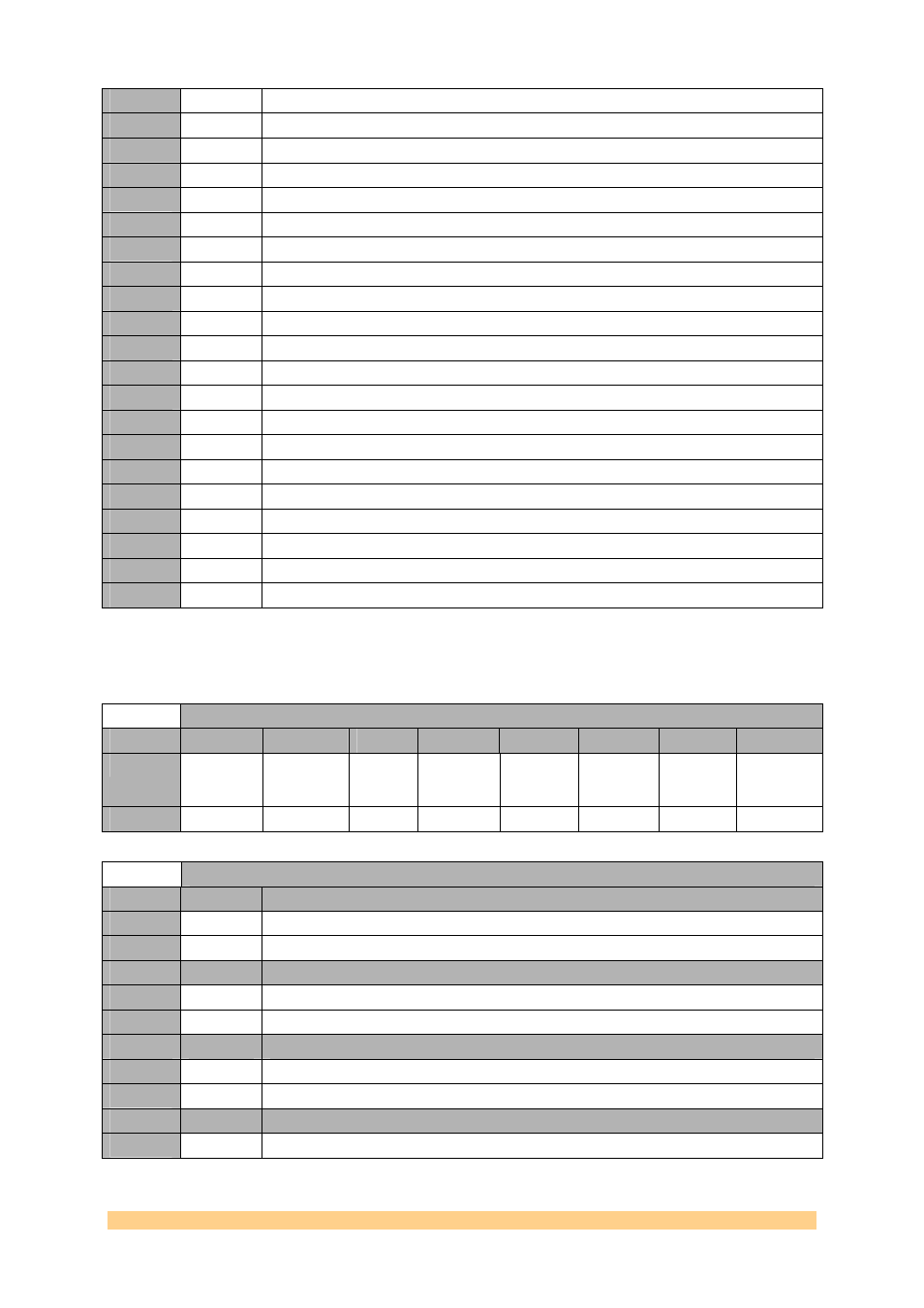
20
10100
DYN Unselected reference to PLL (not available when in differential mode).
19
10011
DYN Selected reference to PLL (differential reference when in differential mode).
18
10010
DYN REF2 clock (not available in differential mode).
17
10001
DYN REF1 clock (differential reference when in differential mode).
16
10000
LVL VS (PLL supply).
15
01111
LVL LD pin comparator output (active high).
14
01110
LVL Holdover active (active high).
13
01101
LVL Digital lock detect (DLD); active low.
12
01100
LVL Selected reference (low = REF1, high = REF2).
11
01011
LVL Status of VCO frequency (active high).
10
01010
LVL (DLD) AND (status of selected reference) AND (status of VCO).
9
01001
LVL (Status REF1 frequency) AND (status REF2 frequency).
8
01000
LVL Status REF2 frequency (active high).
7
01111
LVL Status REF1 frequency (active high).
6
00110
LVL Status of unselected reference (not available in differential mode); active high.
5
00101
LVL Status of selected reference (status of differential reference); active high.
4
00100
DYN Unselected reference to PLL (not available in differential mode).
3
00011
DYN Selected reference to PLL (differential reference when in differential mode).
2
00010
DYN REF2 clock (N/A in differential mode).
1
00001
DYN REF1 clock (differential reference when in differential mode).
0
00000
LVL Ground (dc).
4.6.1.1.20
Clock Generator (AD9516-2) Register 0x1C – PLL Control
7 – 0xF8 (write).
Clock Generator (AD9516-2) Register 0x1C – PLL Control 7 – 0xF8 (write)
Byte
Bit 7
Bit 6
Bit 5
Bit 4
Bit 3
Bit 2
Bit 1
Bit 0
0
Disable
Switchover
Deglitch
Select REF2
Use
REF_SEL
pin
Automatic
Reference
Switchover
Stay on
REF2
REF2
Power on
REF1
Power on
Differential
Reference
Default
‘0’
‘0’
‘0’
‘1’
‘1’
‘0’
‘0’
‘0’
Clock Generator (AD9516-2) Register 0x1C – PLL Control 7 – 0xF8 (write)
Setting
Bit 7
Description (Disable Switchover)
0
0
enable switchover deglitch circuit.
1
1
disable switchover deglitch circuit.
Setting
Bit 6
Description (Select REF2)
0
0
select REF1.
1
1
select REF2.
Setting
Bit 5
Description (Use REF_SEL pin)
0
0
use Register 0x1C<6>.
1
1
use REF_SEL pin.
Setting
Bit 4
Description (Automatic Reference Switchover)
0
0
manual reference switchover.