Sundance SMT712 User Manual
Page 59
User Manual SMT712
Page 59 of 89
Last Edited: 11/12/2012 10:36:00
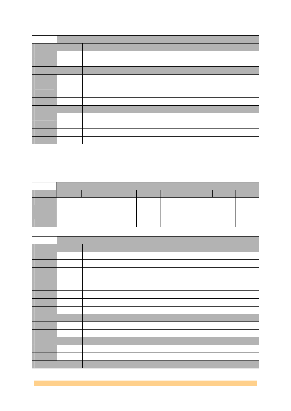
Clock Generator (AD9516-2) Register 0xF4 – OUT5 – 0x14C (write)
Setting
Bit 4
Description (OUT5 Invert)
0
0
noninverting.
1
1
inverting.
Setting
Bit 3..2
Description (OUT5 LVPECL Differential Voltage - (VOD - mV))
3
‘11’
960
2
‘10’
780
1
‘01’
600
0
‘00’
400
Setting
Bit 1..0
Description (OUT5 Power-down)
3
‘11’
Total power-down, reference off; use only if there are no external load resistors. Off.
2
‘10’
Partial power-down, reference on, safe LVPECL power-down.
1
‘01’
Partial power-down, reference on; use only if there are no external load resistors.
0
‘00’
Normal operation.
4.6.1.1.41
Clock Generator (AD9516-2) Register 0x140 – OUT6 –
0x150 (write).
Clock Generator (AD9516-2) Register 0x140 – OUT6 – 0x150 (write)
Byte
Bit 7
Bit 6
Bit 5
Bit 4
Bit 3
Bit 2
Bit 1
Bit 0
0
OUT CMOS Output
Polarity
OUT
LVDS/CMOS
Output
Polarity
OUT
CMOS B
OUT Select
LVDS/CMOS
OUT LVDS Output
Current
OUT
Power-
down
Default
‘01’
‘0’
‘0’
‘0’
‘01’
‘0’
Clock Generator (AD9516-2) Register 0x140 – OUT6 – 0x150 (write)
Setting
Bit 7..5
Description (OUT CMOS Output Polarity - OUTA (CMOS) OUTB (CMOS) OUT (LVDS))
7
‘111’
Noninverting Inverting Inverting
6
‘110’
Inverting Noninverting Noninverting
5
‘101’
Noninverting Noninverting Inverting
4
‘100’
Inverting Inverting Noninverting
3
‘011’
Inverting Inverting Inverting
2
‘010’
Noninverting Noninverting Noninverting
1
‘001’
Inverting Noninverting Inverting
0
‘000’
Noninverting Inverting Noninverting
Setting
Bit 4
Description (OUT CMOS B)
0
0
turn off the CMOS B output.
1
1
turn on the CMOS B output.
Setting
Bit 3
Description (OUT Select LVDS/CMOS)
0
0
LVDS
1
1
CMOS
Setting
Bit 2..1
Description (OUT LVDS Output Current – Current mA / Termination Ohms)