Sundance SMT712 User Manual
Page 70
User Manual SMT712
Page 70 of 89
Last Edited: 11/12/2012 10:36:00
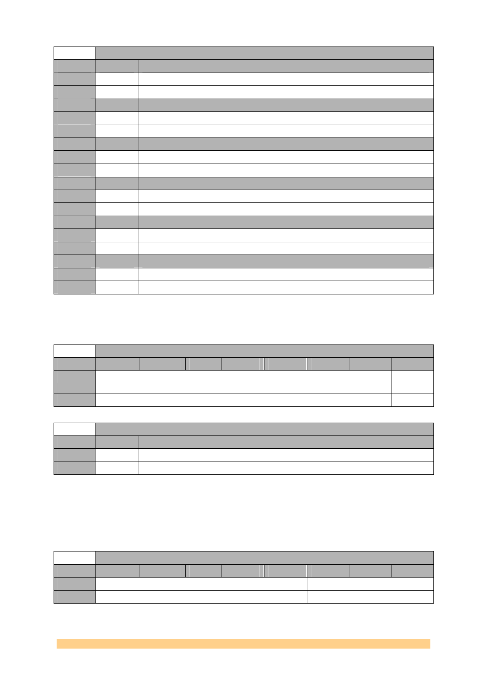
Clock Generator (AD9516-2) Register 0x1A1 – Divider 4– 0x1A4 (write)
Setting
Bit 5
Description (Bypass Divider 4.2)
0
0
use divider.
1
1
bypass divider.
Setting
Bit 4
Description (Bypass Divider 4.1)
0
0
use divider.
1
1
bypass divider.
Setting
Bit 3
Description (Divider 4 Nosync)
0
0
obey chip-level SYNC signal.
1
1
ignore chip-level SYNC signal.
Setting
Bit 2
Description (Divider 4 Force High)
0
0
divider output forced to low.
1
1
divider output forced to high.
Setting
Bit 1
Description (Start High Divider 4.2)
0
0
start low.
1
1
start high.
Setting
Bit 0
Description (Start High Divider 4.1)
0
0
start low.
1
1
start high.
4.6.1.1.63
Clock Generator (AD9516-2) Register 0x1A2 – Divider4 –
0x1A8 (write).
Clock Generator (AD9516-2) Register 0x1A2 – Divder3 – 0x1A8 (write)
Byte
Bit 7
Bit 6
Bit 5
Bit 4
Bit 3
Bit 2
Bit 1
Bit 0
0
Reserved
Divider
DCCOFF
Default
‘000000’
‘0’
Clock Generator (AD9516-2) Register 0x1A2 – Divder3 – 0x1A8 (write)
Setting
Bit 0
Description (Divider DCCOFF)
1
1
disable duty-cycle correction.
0
0
enable duty-cycle correction.
4.6.1.1.64
Clock Generator (AD9516-2) Register 0x1E0 – VCO
Divider – 0x1AC (write).
Clock Generator (AD9516-2) Register 0x1E0 – VCO Divider – 0x1AC (write)
Byte
Bit 7
Bit 6
Bit 5
Bit 4
Bit 3
Bit 2
Bit 1
Bit 0
0
Reserved
VCO Divider
Default
‘00000’
‘010’