Sundance SMT712 User Manual
Page 45
User Manual SMT712
Page 45 of 89
Last Edited: 11/12/2012 10:36:00
1
01
4
0
00
2
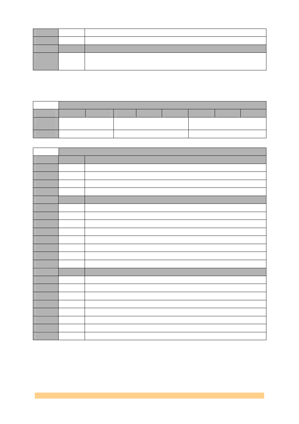
Setting
Bit 0
Description (VCO Calibration Now)
0
0
Bit used to initiate the VCO calibration. This bit must be toggled from 0 to 1 in the active
registers. The sequence to initiate a calibration is: program to a 0, followed by an update
bit ; then programmed to 1, followed by another update bit
4.6.1.1.17
Clock Generator (AD9516-2) Register 0x19 – PLL Control
4 – 0xEC (write).
Clock Generator (AD9516-2) Register 0x19 – PLL Control 4 – 0xEC (write)
Byte
Bit 7
Bit 6
Bit 5
Bit 4
Bit 3
Bit 2
Bit 1
Bit 0
0
R, A, B counters /SYNC
Pin reset
R Path Delay
N Path Delay
Default
‘00’
‘000’
‘000’
Clock Generator (AD9516-2) Register 0x19 – PLL Control 4 – 0xEC (write)
Setting
Bit 7..6
Description (Charge Pump Current)
3
11
Do nothing on SYNC.
2
10
Synchronous reset.
1
01
Asynchronous reset.
0
00
Do nothing on SYNC (default).
Setting
Bit 5..3
Description (R Path Delay)
7
111
6
110
5
101
4
100
3
011
2
010
1
001
0
000
Setting
Bit 2..0
Description (N Path Delay)
7
111
6
110
5
101
4
100
3
011
2
010
1
001
0
000