Mechanical pump - pulser connections, Pulse rate, Interface connections – Gasboy FuelOmat system 8 Popt Commverter User Manual
Page 68: Figure 2-43. mpi-c j2 and j3 jumpers
2.13.2.
Mechanical Pump - Pulser Connections
This paragraph describes the required wiring connections between the pulser in the mechanical
pump and the MPI-C. The system can accept many types of pulsers, please contact Gilbarco for
more information. Two types of pulsers can be found in pumps:
- Electronic pulser
- Mechanical pulser
Connect the MPI-C card to the Pulser in accordance to its characteristics.
2.13.2.1. Pulse Rate
The MPI-C may be configured to work with normal and high rate pulses (see Table 2-5), as may be
generated by Electronic Pulsers. The wiring is identical for both cases, yet the technician is required
to change jumper settings as detailed below. It is highly recommended to use normal rate pulsers to
prevent noise.
Table 2-5. Pulse Rate Specifications
Parameter
Normal Rate
High Rate
Minimum:7 VDC
Minimum: 4VDC
Input Voltage
Maximum: 15 VDC
Maximum: 12 VDC
Pulse Rate
Maximum: 0.5 KHz
Maximum: 5 KHz
Cycle Width
Minimum: 2 ms
Minimum: 0.2 ms
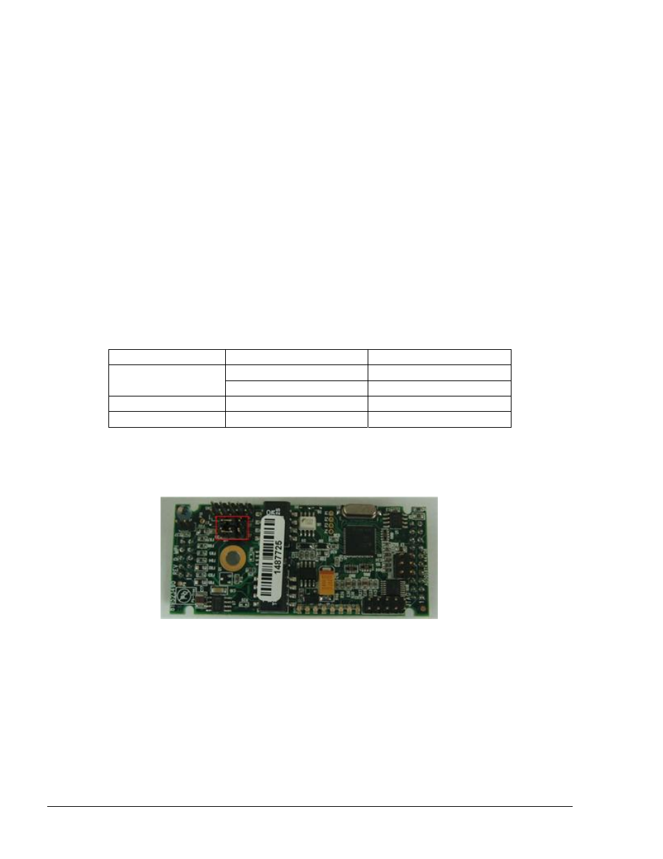
By default the MPI-C card is set to work with Normal Rate pulses: J2 and J3 jumpers' pins 1 and 2
are shorted (see Figure 2-44). In cases where the pump outputs high rate pulses, short pins 2 and 3.
Figure 2-44. MPI-C J2 and J3 Jumpers
2.13.2.2. Interface Connections
Figure 2-45 shows Mechanical Pump Interface Connections, including Mechanical and Electronic
Pulsers.
8 Port CommVerter Operation and Installation Manual
64