Figure 2-15. current loop module jumpers – Gasboy FuelOmat system 8 Popt Commverter User Manual
Page 40
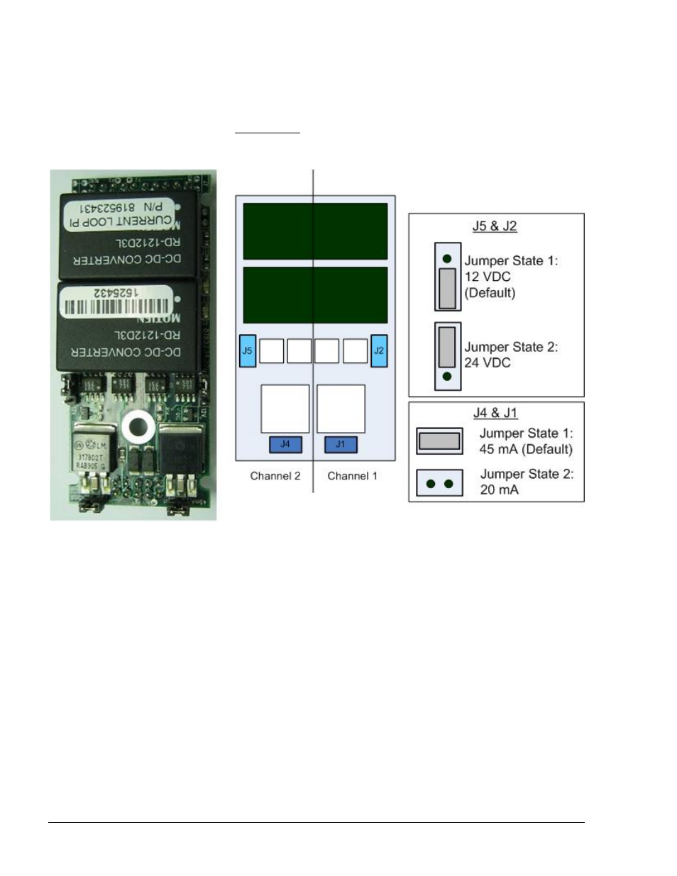
Jumpers J1, J4 installed; (for old PCBs J3, J6 also installed)
for 45 mA (default) consumption
Jumpers J1, J4 not installed; (for old PCBs J3, J6 also not
installed) for 20 mA consumption
Figure 2-15. Current Loop Module Jumpers
2.7.4. Current Loop Electronic Devices (Pump or any Current Loop Devices)
The wiring for the Current Loop electronic pump is provided as follows:
Figure 2-18 shows the specific wiring connections between the 8 Port Current Loop card
and Current Loop pumps. Figure 2-16 and Figure 2-17 show the connection between two
Current Loop twin-pumps and the Terminal Block: In cases where connecting twin pumps
on a single cluster (module channel), set each pump with a different head number. If
connecting each twin pump on dedicated cluster, there is no need to reprogram the pump.
Pumps with identical Head number cannot be connected to the same Cluster.
8 Port CommVerter Operation and Installation Manual
36
- 216S (18 pages)
- Atlas Fuel Systems Site Prep Manual (42 pages)
- Atlas Technician Programming Quick Ref (2 pages)
- ATC M05819K00X Kits (28 pages)
- Atlas Fuel Systems Owner Manual (80 pages)
- Gilbarco Global Pumping Unit Operation Manual (42 pages)
- 26 (7 pages)
- Atlas Valve Replacement Kits (10 pages)
- Atlas Fuel Systems Installation Manual (100 pages)
- 9120K (8 pages)
- 9820K (6 pages)
- Atlas Single Std. Inlet Centering Kit (8 pages)
- 8800 Atlas (1 page)
- 9120K Series Service Manual (40 pages)
- 9800A Atlas (6 pages)
- 9800 Atlas (14 pages)
- 9800 Atlas (20 pages)
- M08400 (6 pages)
- 9100 Series (8 pages)
- 9820K Series Installation (62 pages)
- 9853K (8 pages)
- 9216KTW (36 pages)
- Recommended Spare Atlas (14 pages)
- DEF Atlas (28 pages)
- 9820K Series (12 pages)
- 9800Q (1 page)
- Q Series (3 pages)
- 8753E (2 pages)
- 9152AXTW2 (1 page)
- 8800E (2 pages)
- 8800E (1 page)
- 9820Q Series (1 page)
- Atlas Start-up (230 pages)
- 9800Q Front Load Vapor (2 pages)
- 215A (1 page)
- 9800A (4 pages)
- 9820A (1 page)
- 2600A (3 pages)
- 2600A (12 pages)
- 2600A (2 pages)
- 216A (31 pages)
- 215A (2 pages)
- 9800Q Vapor (2 pages)
- Lamp Kit (2 pages)
- 9120Q Pulser (1 page)