Tokheim connector pinout, Tokheim module jumpers – Gasboy FuelOmat system 8 Popt Commverter User Manual
Page 53
NOTE
There is no external indication of the LEDs status.
Remove the Commverter cover to reveal the module
LEDs.
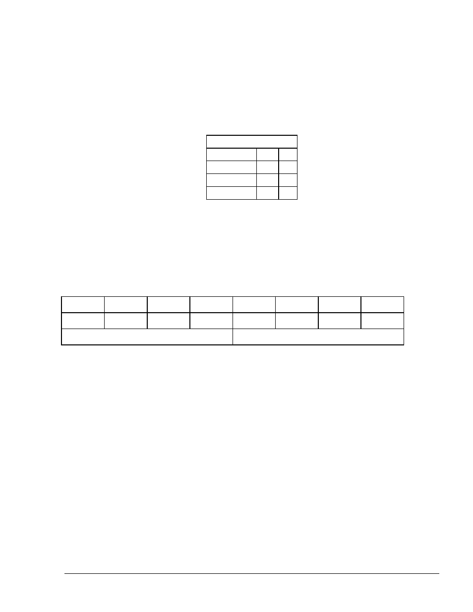
LEDs Indication
Connector Side
Channel 1
Rx
D1
Channel 1
Tx
D2
Channel 2
Rx
D3
Channel 2
Tx
D4
LED Blinking
– Communication on
LED Off
– No communication
2.8.1.
Tokheim Connector Pinout
The following pinout is required for the LAN to Tokheim application, for all Tokheim brand
pumps.
8 7 6 5 4 3 2 1
G COM TTC TTD G COM TTC TTD
Channel 2
Channel 1
2.8.2.
Tokheim Module Jumpers
This module can be set to 5V or 12V according to the Pump Interface requirement. There are two
jumpers that determine the voltage level, as follows:
o
Jumpers J1, J2 installed: 5V
o
Jumpers J1, J2 removed: 12V
2.8.3. Tokheim Electronic Devices (Pump or any Tokheim Devices)
The wiring for the Tokheim electronic pump is provided as follows:
Figure 2-29 shows the specific wiring connections between the 8 Port Tokheim card
and the Tokheim pump nozzle, and the terminals that differ from the Mechanical
Pump.
8 Port CommVerter Operation and Installation Manual
49