Table 3-6, Zone 2 connector p23 pin assignment, Controls, indicators, and connectors – Artesyn ATCA-7368 Installation and Use (June 2014) User Manual
Page 65
Controls, Indicators, and Connectors
ATCA-7368 Installation and Use (6806800M12D)
65
8
IPMC ISC PC3
Hardware Address Bit 3
9
IPMC ISC PD4
Hardware Address Bit 4
10
IPMC ISC PD5
Hardware Address Bit 5
11
IPMC ISC PD6
Hardware Address Bit 6
12
IPMC ISC PD7
Hardware Address Bit 7
13
IPMC IMC PD0
IPMB Clock Port A
14
IPMC IMC PD1
IPMB Data Port A
15
IPMC ISC PC5
IPMB Clock Port B
16
IPMC ISC PC4
IPMB Data Port A
17 - 24
Not used
Not used
25
Shelf Ground
Shelf Ground
26
Logic Ground
Logic Ground
27
Power Building Block
Enable B
28
Power Building Block
Voltage Return A
29
Power Building Block
Voltage Return B
30
Power Building Block
Early -48V A
31
Power Building Block
Early -48V B
32
Power Building Block
Enable A
33
Power Building Block
-48V A
34
Power Building Block
-48V A
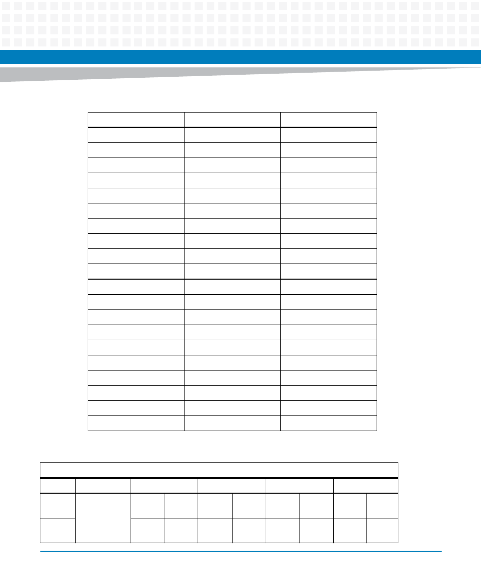
Table 3-5 Zone 1 Connector P1 Pin Assignment
Contact Number
Destination
Description
Table 3-6 Zone 2 Connector P23 Pin Assignment
P23
Row #
Interface
Col AB
Col CD
Col EF
Col GH
1
Fabric
Channel 2
F2[2]_
TX+
F2[2]_
TX-
F2[2]_
RX+
F2[2]_
RX-
F2[3]_
TX+
F2[3]_
TX-
F2[3]_
RX+
F2[3]_
RX-
2
F2[0]_
TX+
F2[0]_
TX-
F2[0]_
RX+
F2[0]_
RX-
F2[1]_
TX+
F2[1]_
TX-
F2[1]_
RX+
F2[1]_
RX-