Altera RLDRAM II Controller MegaCore Function User Manual
Page 14
2–4
MegaCore Version 9.1
Altera Corporation
RLDRAM II Controller MegaCore Function User Guide
November 2009
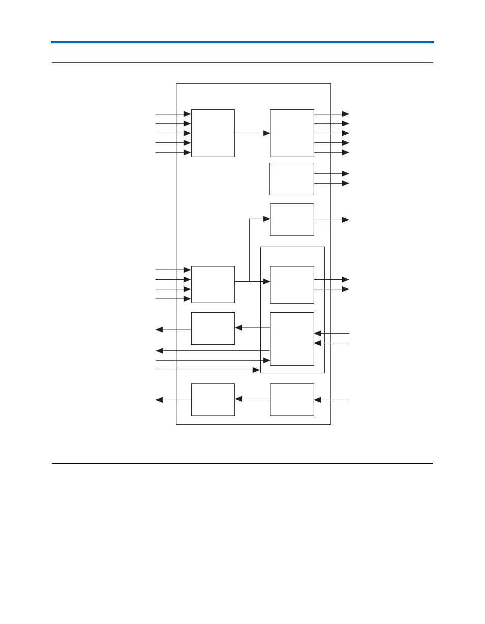
Block Description
Figure 2–2. Datapath Block Diagram
Note to
:
(1)
The default signal is <signal>_0. When you specify additional address and command busses, both <signal>_0 and
<signal>_1 are present.
The datapath performs the following functions:
■
Interfaces to CIO or SIO RLDRAM II devices
■
Outputs write data to the RLDRAM II interface
■
Captures RLDRAM II read data and data valid (QVLD) signals with:
●
In DQS mode, a delayed rldramii_qk[] generated by the
dedicated DQS delay circuitry
●
In non-DQS mode, an external capture clock
Optional
Pipeline
Registers
Datapath
rldramii_clk[]
Address &
Command
Output
Registers
Optional
Pipeline
Registers
Write
Data
Logic
Optional
Pipeline
Registers
Read
Data
Logic
Memory
Clock
Generator
rldramii_clk_n[]
Optional
Pipeline
Registers
QVLD
Group
DM
Group
DQS Group
control_dm[]
control_doing_wr
control_wdata[]
control_wdata_valid
control_a[]
control_ba[]
control_cs_n
control_ref_n
control_we_n
control_rdata[]
capture_clk[]
non_dqs_capture_clk
dqs_delay_ctrl[]
control_qvld[]
rldramii_dq[]
rldramii_d[]
rldramii_q[]
rldramii_qk[]
rldramii_qvld[]
rldramii_dm[]
rldramii_a_0[]
rldramii_ba_0[]
rldramii_cs_n_0
rldramii_ref_n_0
rldramii_we_n_0