Switch assignment, End point adjustments, Switch assignment end point adjustments – HITEC Flash 7 User Manual
Page 48: 7 channel 2.4 ghz aircraft computer radio system, 47 switch assignment
7 Channel 2.4 GHz Aircraft Computer Radio System
7 Channel 2.4 GHz Aircraft Computer Radio System
Section 4: Common Model Programming Menu
47
Switch Assignment
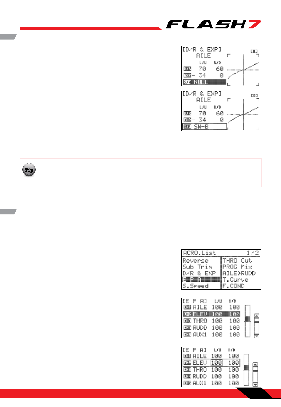
17. Scroll to highlight the S/W field and press the jog dial to
activate the menu.
18. Scroll to select the switch you have chosen to control dual
rates for this function and press the jog dial to confirm your
selection.
19. Physically move the switch to the desired position for low-
rates.
Repeat steps 5-16 to input low-rate throws and exponential values for the selected function.
Repeat steps 4-19 for each control function.
20. Press the back button to return to the model menu.
The final settings in the D/R & EXP menu should reflect the model aircraft manufacturer’s
suggested control surface deflections for each function. Some manufacturers also provide
suggested exponential values.
Note
Tip
Tip
Tip
Caution
The End Point Adjustment (EPA) feature allows you to fine tune the maximum servo movement for every
channel. This capability is very useful when dealing with models that require small control movements or
in cases where binding/damage could occur from excessive control movement.
End Point Adjustments
1. From the model menu, scroll to highlight “EPA” and press the
jog dial once to enter the EPA menu.
2. Scroll to the control surface to be adjusted and press the jog
dial to activate the EPA sub-menu.
3. Scroll to highlight the “L/U” (left/up) field and press the jog dial
to activate the menu.
4. Rotate the jog dial to increase (clockwise) or decrease
(counter-clockwise) the desired left (AILE, RUDD) or up (ELEV)
servo endpoint. Press the jog dial to confirm your input.