Servo manager, Advanced telemetry sensors, Servo manager advanced telemetry sensors – HITEC Flash 7 User Manual
Page 100: 7 channel 2.4 ghz aircraft computer radio system, 99 battery cont
7 Channel 2.4 GHz Aircraft Computer Radio System
7 Channel 2.4 GHz Aircraft Computer Radio System
Section 7: Using the Telemtry System
99
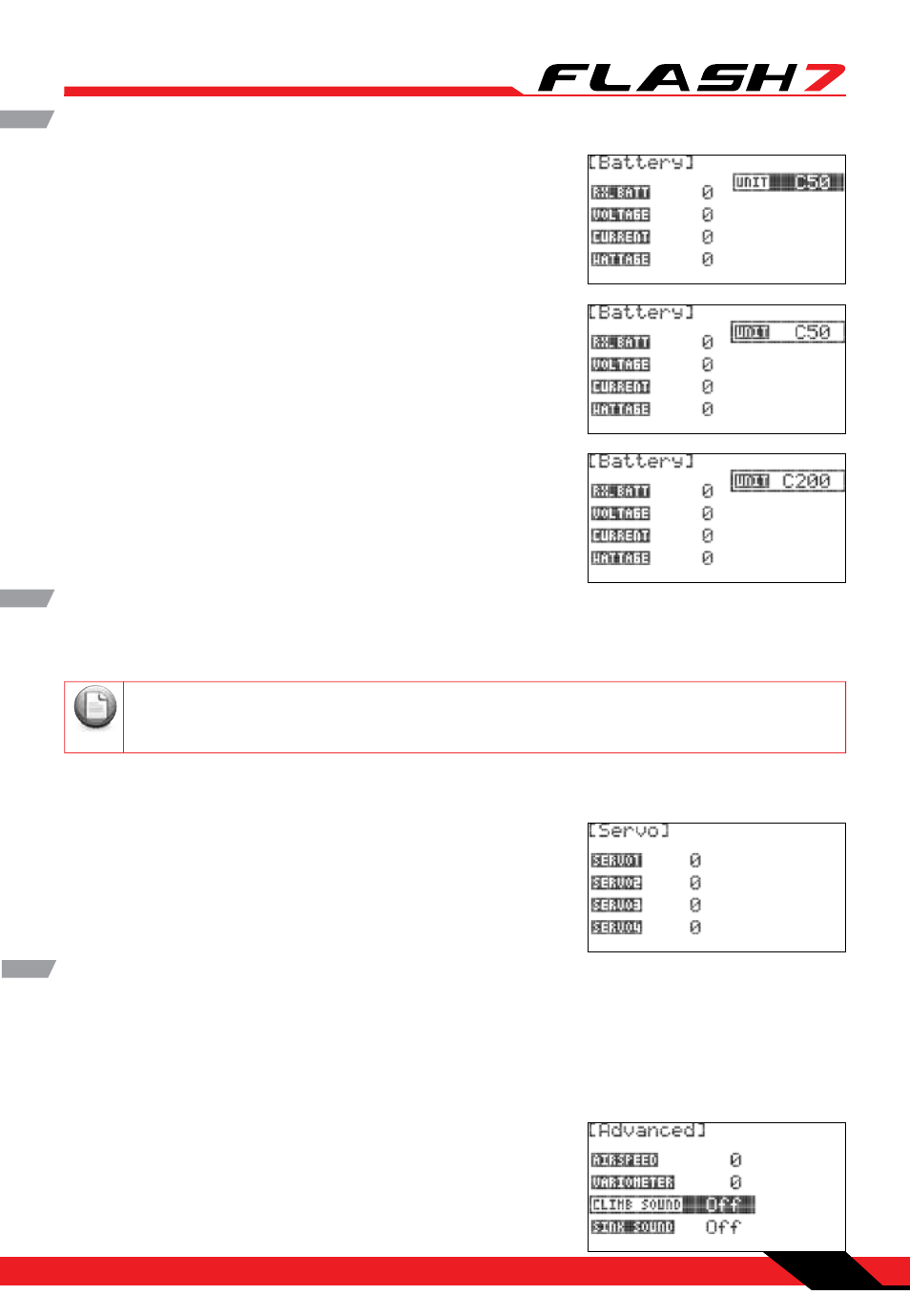
Battery cont.
1. From the sensor menu, rotate the jog dial to highlight
“BATTERY” and press the jog dial once to enter the battery
menu.
2. Press the jog dial again to activate the “UNIT” field.
3. Scroll to select “C50” if using the 50-amp current sensor or
“C200” if using the 200-amp current sensor. Press the jog dial
to confirm your selection.
4. Press the back button to return to the sensor menu.
Servo Manager
The Servo screen displays the current draw for each servo attached to the outputs of the Servo Manager
sensor.
1. From the sensor menu, rotate the jog dial to highlight “Servo”
and press the jog dial once to enter the Servo screen.
2. Press the back button to return to the sensor menu.
If multiple servos are attached to a single sensor output using a Y-harness, the display will show
the total amperage for all servos connected to that output.
Note
Tip
Tip
Tip
Required Sensor: HTS-SM Servo Manager Sensor (compatible only with the HTS-SS Advanced Sensor
Station).
Advanced Telemetry Sensors
The Advanced screen displays airspeed data collected from Hitec’s dedicated airspeed sensor (not GPS),
as well as rate-of-climb data collected by a variometer.
Required Sensor: HTS-AS Air Speed Sensor and HTS-VM Variometer Sensor (both sensors are compatible
only with the HTS-SS Advanced Sensor Station).
1. From the sensor menu, rotate the jog dial to highlight
“Advanced” and press the jog dial once to enter the advanced
menu.