Appendix a: hardware adjustment, Stick length adjustment, Stick lever tension adjustment / mode change – HITEC Flash 7 User Manual
Page 102: Hardware adjustments, 7 channel 2.4 ghz aircraft computer radio system
7 Channel 2.4 GHz Aircraft Computer Radio System
7 Channel 2.4 GHz Aircraft Computer Radio System
Section 7: Using the Telemtry System
101
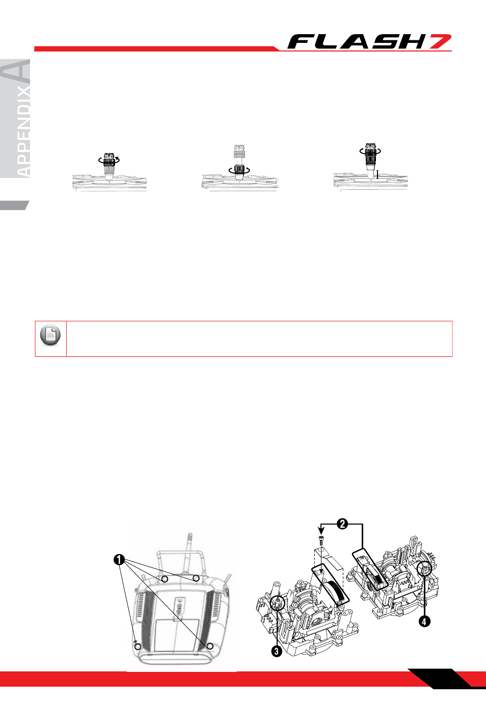
Stick Length Adjustment
Stick Lever Tension Adjustment / Mode Change
Hands come in all sizes so, to accommodate everyone, we use a two piece stick “top” that can be adjusted
to fit a wide variety of users.
Separate the top from the bottom piece and adjust the top piece to the length required.
Screw the bottom up against the top piece to “jam” lock everything into position.
Stick Lever Tension Adjustment
You may adjust the stick tension of your sticks to provide the “feel” that you like for flying. To adjust your
springs, you’ll have to remove the rear case of the transmitter. Using a screwdriver, remove the four screws
that hold the transmitter’s rear cover into position and put them in a safe place.
Gently ease off the transmitter’s rear cover. Now you’ll see the view shown. Using a small cross-point
screwdriver, rotate the adjusting screw for each stick for the desired spring tension. The tension increases
when the adjusting screw is turned clockwise, and decreases for counterclockwise motion.
Change to ‘Mode 1’ Configuration
All Flash 7 systems sold in the US are in ‘Mode 2’ format. However, you may wish to use Flash 7 in ‘mode 1’ format.
There is a menu choice for this option in the Initial Set-Up function menu described on Page 26.
After selecting ‘Mode 1’ in the Initial Set-Up Menu, you must do the following hardware set-up in order to
change the transmitter:
Note
Please use 1.5mm hex key for gimbals’ tension adjustment and mode changes.
When you are satisfied with the spring tensions, you may close the transmitter.
Very carefully reinstall the rear cover.
When the cover is properly in place, tighten the four screws.
1. Remove all the four philips screws from the back of the case.
2. Unscrew a hex screw to remove the Copper Ratchet from where it is located and move it to the other side.
3. Tighten up the tension spring hex screw on the new location.
4. Loosen up the tension spring hex screw on the original location.
5. Re-assemble the case.