Lonpoint hardware guide 8-3 – Echelon LonPoint Module User Manual
Page 87
LonPoint Hardware Guide
8-3
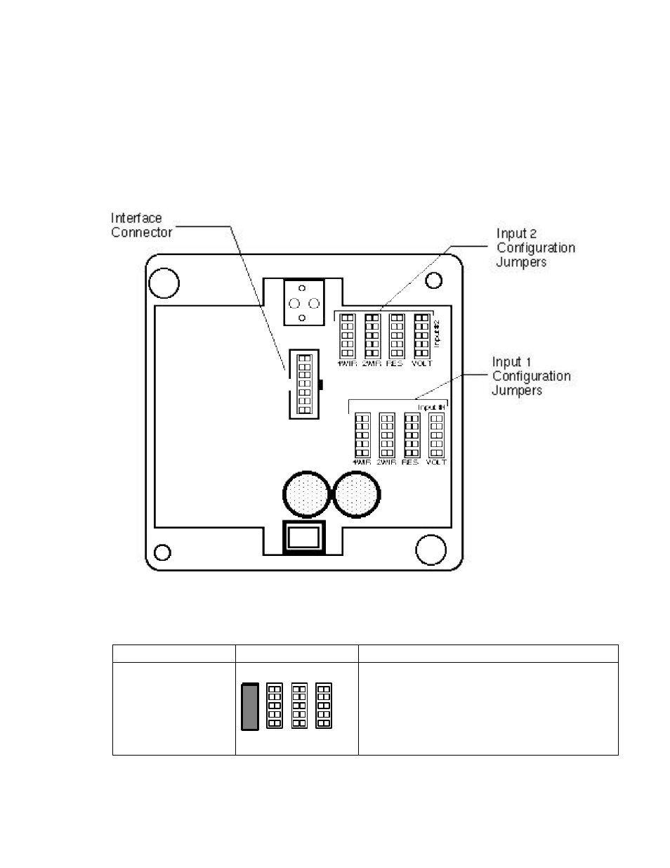
The AI-10 module includes four 5 x 2 jumper blocks for each input. These jumper
blocks, labeled 2WIR, 4WIR, RES, and VOLT, are used to configure the module for
the type of analog input signal that will be monitored (figure 8.2); using an incorrect
jumper setting will result in improper input supervision and could cause damage to
the module and/or the sensor. Each of the two sensor inputs may be configured
differently. Table 8.1 presents the correct jumper position for different types of
analog inputs.
Figure 8.2 LonPoint AI-10 Jumper Block Settings - Rear Panel
Table 8.1 AI-10 Analog Input Module Wiring Connections
Function
Jumper Position
Description
Input 1
4-Wire 0-24mA
Remotely Powered
Input #1
4WIR
RES
2WIR
VOLT
This setting is used for connecting 0-20mA,
4-20mA, 4-24mA, or 0-24mA intelligent
transmitters that are powered by either their own
power supply or a separate power supply. The
maximum allowable current range is 0-25mA. In
this setting the AI-10 does not supply power to the
current loop.