I/o cabling, Power cabling, Terminator for tp/xf-1250 channel – Echelon LonPoint Module User Manual
Page 31: Lonpoint hardware guide 3-9
LonPoint Hardware Guide
3-9
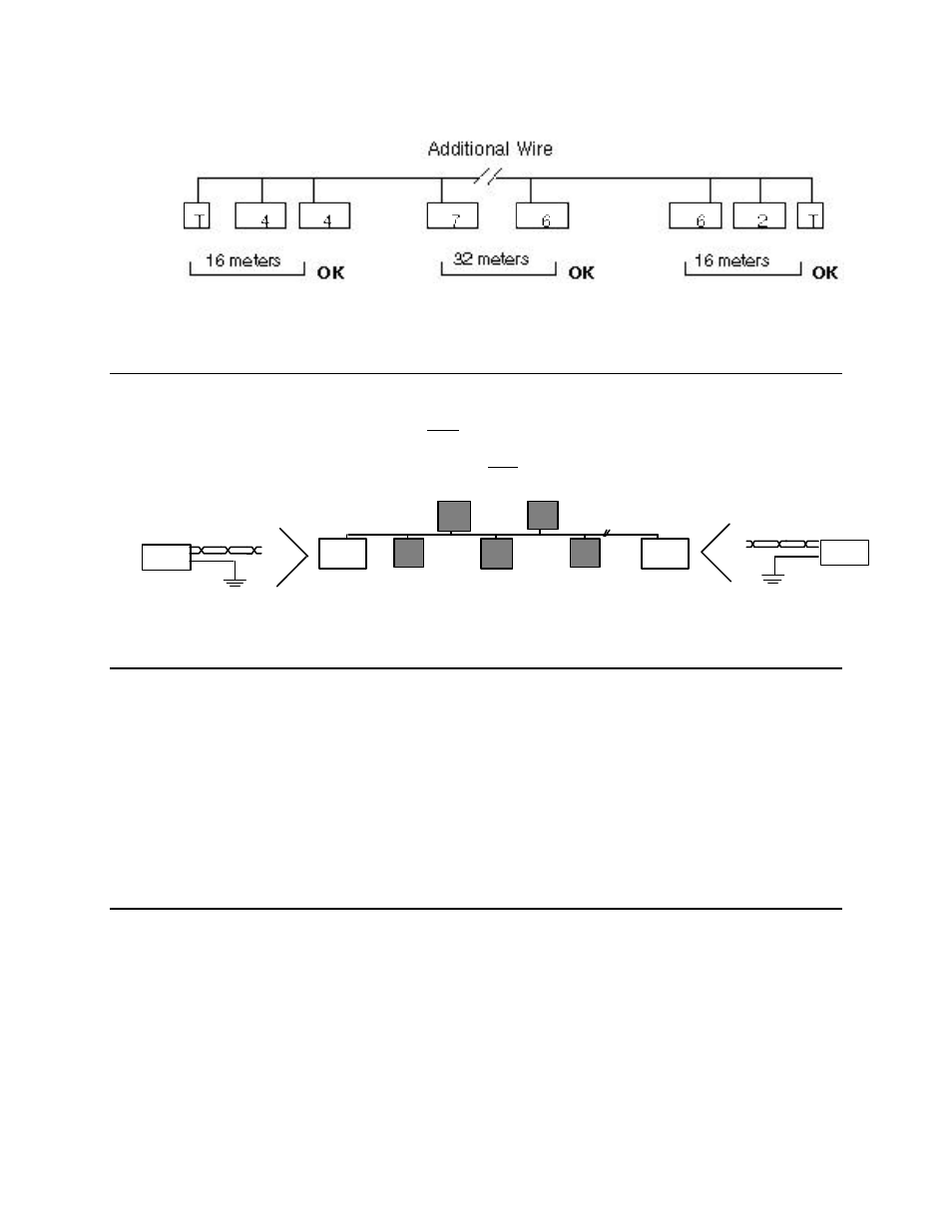
Figure 3.12 Using Additional Bus Cable to Meet the 8-in-16 Topology Rule
Terminator for TP/XF-1250 Channel
It is necessary to terminate both endpoints of the TP/XF-1250 channel twisted pair
bus for proper data transmission performance. Failure to terminate the bus will
degrade network performance. Use only the Model 44200 Terminator, and connect
it as shown in figure 3.13.
orange
Network
green
44200
Terminator
Termination
Termination
orange
Network
green
44200
Terminator
Figure 3.13 Double Termination for Bus Topology (Two Model 44200 Terminators)
I/O Cabling
The installer generally has wide latitude in the type of cabling selected for the I/O.
It is good practice to ensure that all I/O cabling is made from twisted pair wire, as
this has the advantage of minimizing susceptibility to differential noise. If the sensor
or actuator requires a shield then a ground will have to be provided in the electrical
box since the LonPoint modules are floating and do not include a ground screw
connection. Note when selecting the I/O cabling that the Base Plate screw terminals
accommodate wire guages from 24AWG/0.5mm to 12AWG/2mm. In all cases, use at
least 90°C rated wire.
Power Cabling
It is important to note that a maximum of 16 Amperes RMS at 24VAC RMS can be
passed through the internal jumpers on the Power terminals of the Type 1/2 Base
Plates, 10 Amperes RMS at 24 VAC RMS for Type 1D/2D DIN Base Plates using
Jumper Plugs. This means that if power wiring is looped in and out of the power
terminals of the LonPoint Base Plates, the current load presented by all of the
LonPoint modules and any other devices powered by that circuit must be 16
Amperes ( 10 Amperes for Type 1D/2D DIN Base Plates using Jumper Plugs), as