Echelon LonPoint Module User Manual
Page 64
4-28
Installation and Wiring of Base Plates
Table 4.4 Type 2D Base Plate Terminal Block Connections
Terminal Number
Function
1 -4
Network A
5
Cable shield, if used, internally connected to terminal 14
6 - 9
Power
10 and 12
None
Jumpered together internally, may be used to land extra wires
11 and 13
None
Jumpered together internally, may be used to land extra wires
14
Cable shield, if used, internally connected to terminal 5
15 - 18
Network B
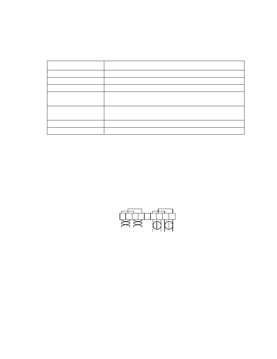
Two sets of screws are provided for both the power and network wiring connections.
These connections are internally jumpered on the Type 2D Base Plate PCB to
provide continuity of the network and power wiring, even if no LonPoint module is
installed, as shown in figure 4.26. This feature permits the Base Plate wiring to be
pre-installed and the network and power circuits checked for continuity throughout
the installation, before a single LonPoint module is ever installed. This feature also
prevents network and power interruptions as a result of hot-swapping LonPoint
modules during commissioning or service operations. Finally, providing two sets of
screw terminals permits incoming and outgoing to be landed at separate screw
terminals without the need to insert more than one wire in any given screw
terminal.
1 2 3 4 5 6 7 8 9
Network
16-30VAC or VDC
Figure 4.26 Base Plate Power and Network Wiring Connections