Echelon LonPoint Module User Manual
Page 21
LonPoint Hardware Guide
2-11
Analog Output
This symbol designates the I/O as an analog output and is accompanied by an I/O
Number.
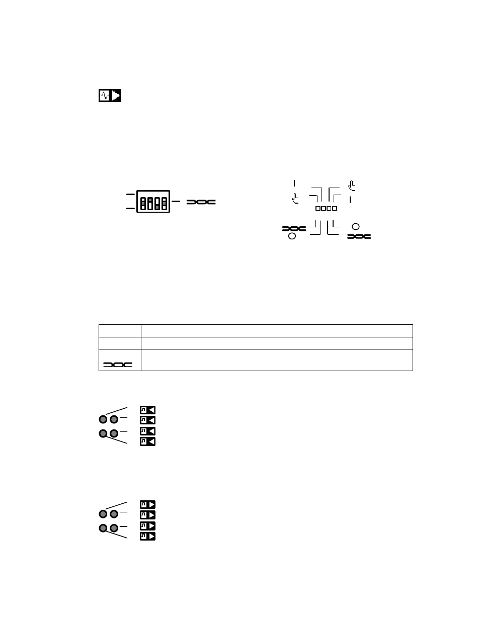
Hand/Off/Auto Switch
1 2 3 4
1
0
1 2 3 4
1
2
1 2 3 4
DO-10 Hand/Off/Auto Switch
DIO-10 Hand/Off/Auto Switch
The DO-10 and DIO-10 modules include a Hand/Off/Auto switch that allows the user to
determine the mode of operation of the outputs. One three-position switch is provided
for each of the four outputs. The switch positions function as follows:
1
Output turned ON (voltage level high or relay actuated)
0
Output turned OFF (voltage level low or relay not actuated)
Output state is determined automatically according configuration programs
loaded into the LonPoint modules on the network.
Input Status LEDs
1
2
3
4
Input status LEDs indicate the state of the inputs.
Output Status LEDs
1
2
3
4
Output status LEDs indicate the logical state of the outputs.