Lonpoint interface and router module symbology, Lonpoint hardware guide 2-9, Di-10 – Echelon LonPoint Module User Manual
Page 19
LonPoint Hardware Guide
2-9
LonPoint Interface and Router Module Symbology
The front and rear panels of the LonPoint Modules and Base Plates contain legends that
identify the function of the module and its various LEDs, switches, and network
connector. A common legend marking scheme is used that allows the module to be
rotated clockwise 90° and still be legible, in the event that the mounting enclosure is
installed off axis. The symbols used are as follows:
Network Connector
Each module includes a network connector for accessing the TP/FT-10 network directly
from the front panel. This feature is intended to allow a laptop PC equipped with a
Model 73200 PCC-10 PC Card and Model 78303 cable assembly to plug into the
LonPoint module and program, monitor, troubleshoot, or update a LonPoint system.
The 3.5mm mating plug is a Hosiden 315-0201-01 miniature phone jack, or equal.
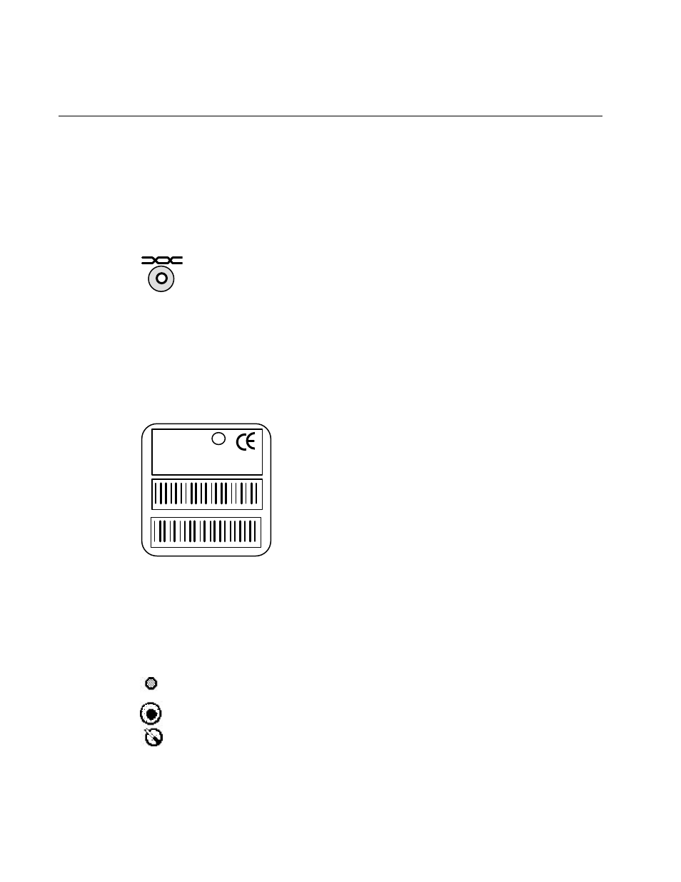
Front Panel Label
DI-10 MODEL 41100 ID NUMBER
DI-10 MODEL 41100 ID NUMBER
DI-10
MODEL 41100 972
SW VERSION 3.0
ID NUMBER
INPUT: 0-32VDC
LISTED 178K
ENERGY MANAGEMENT
EQUIPMENT SUBASSEMBLY
c
us
m
L
U
®
Every module is supplied with a front panel label that identifies the model number and
software version number of the module. The front panel label also includes two peel-off
Code 39 bar code labels on which are printed the Neuron Chip ID of that module (LPR
modules have two Neuron Chip IDs, one per channel). These labels are intended to
assist the installer during installation time, and may be removed from the module and
placed on installation drawings for reference purposes.
Service Switch/LED
Every module includes a service switch and LED which may be used during module
installation and to identify configured and unconfigured modules.