Dio-10 module digital inputs – Echelon LonPoint Module User Manual
Page 75
Installing the DIO-10 Input/Output Modules
6-3
The DIO-10 module is intalled in a Type 1 or Type 1D Base Plate. Wiring connections to the
DIO-10 module are presented in table 6.1. Specifications for the DIO-10 module are shown in
table 6.4.
Table 6.1 DIO-10 Digital Input/Output Module Wiring Connections
Screw Terminal
Wiring Connection
1 and 2
Incoming network wiring, TP/FT-10 channel, polarity-
insensitive
3 and 4
Outgoing network wiring, TP/FT-10 channel, polarity-
insensitive
5
Unused
6 and 7
Incoming power wiring, 16-30VAC or VDC, 4.75VA, polarity-
insensitive. If using DC power, it is good practice to maintain
continuity of the power polarity throughout the network:
terminals 6 and 8 should be the same polarity, and terminals
7 and 9 should be the same polarity.
10
Output 1 relay wiper
11
Output 1 normally closed output
12
Output 1 normally open output
13
Output 2 relay wiper
14
Output 2 normally closed output
15
Output 2 normally open input
16
- input of digital input 1
17
+ input of digital input common
18
- input of digital input 2
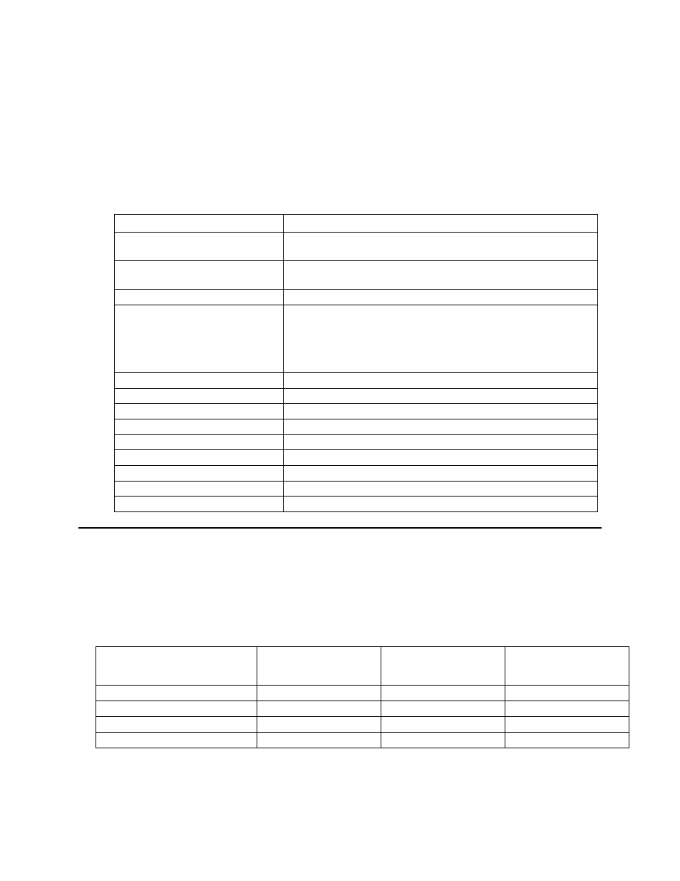
DIO-10 Module Digital Inputs
The following table lists the input switching levels of the DIO-10 Module
digital inputs (over full operational range).
Table 6.2 DIO-10 Module Input Switching Levels
Input Range
Maximum Positive
Threshold Voltage
(Vpmax) [V]
Minimum Negative
Threshold Voltage
(Vnmin) [V]
Minimum Hysterisis
(Vhmin) [V]
0 - 5, dry contacts
3.85
1.35
0.40
0 - 12 V
9.48
3.15
0.93
0 - 24 V
19.28
6.28
1.86
0 - 31 V
24.90
8.08
2.39