Echelon LonPoint Module User Manual
Page 57
LonPoint Hardware Guide
4-21
gang PVC switch box (Raco 7834 or equal), and Echelon’s Model 48001 EuroBox for
wall and 35mm DIN rail applications.
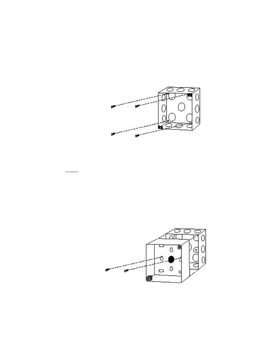
A 4” square electrical enclosures should be either affixed to a wall or to equipment using
suitable mounting screws, or recessed using a suitable mounting clamp (figure 4.19). Due
to variations in the location of knock-outs, care must be taken to ensure that 3/4” conduit
fittings do not interfere with the Base Plate when it is installed in the electrical box; 1/2”
conduit fittings have not been found to cause an interference problem.
Figure 4.19 4” Square Electrical Box Mounting
There are four mounting options if Echelon’s EuroBox is used. The Eurobox
requires the installer to drill cabling holes: ensure that suitable holes are drilled
prior to mounting. In order to avoid interference with a Type 1 or Type 2 Base
Plate, all glands and conduit fittings must be located within 1.4”/35cm of the bottom
of the box (as measured from the outside of the box). Wire glands and conduit
fittings must not extend more than 0.63”/16mm into the EuroBox in order to prevent
associated cabling from interfering with the Base Plate screw terminals.
For UK applications, a second mounting option is to affix the EuroBox to a single
gang 25mm BS4662 flush mounting box (MK 866ZIC or similar). Two keyhole slots
are provided in the EuroBox to accomodate the flush mounting box as shown in
figure 4.20. Use screws with flush mounting and ensure that suitable cabling holes
are drilled in the Eurobox prior to mounting, as discussed above.
Figure 4.20 MK Electrical Box Mounting the EuroBox