Lonpoint di-10 digital input module, 2 installing the di-10 digital input module, Di-10 – Echelon LonPoint Module User Manual
Page 70
5-2
Installing the DI-10 Digital Input Module
LonPoint DI-10 Digital Input Module
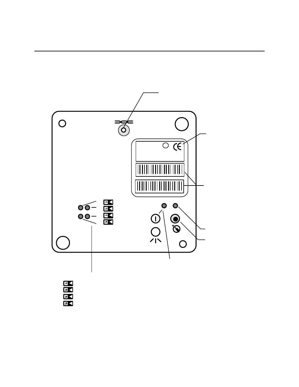
The front panel of the DI-10 module is shown in figure 5.1. There are no user-
configured jumper blocks or other adjustable controls on the DI-10 module. A
separate front panel LED is provided for each intput.
Network Access Jack; Use
With Echelon PCC-10 Cable
Model 78303
Peel-Off Code 39
Format Bar Code of
LonPoint Interface
Neuron Chip ID
Number
LonPoint Interface
Model and Software
Revision
Service LED
Service Switch
Power/Wink LED:
Power ON: Illuminated Continuously
Wink: Flashing
Lo
nP
oi
nt
™
In
te
rfa
ce
1
2
3
4
Digital Input Status LEDs
Digital Input 1 LED
Digital Input 2 LED
Digital Input 3 LED
Digital Input 4 LED
1
2
3
4
DI-10 MODEL 41100 ID NUMBER
DI-10 MODEL 41100 ID NUMBER
DI-10
MODEL 41100 972
SW VERSION 3.0
ID NUMBER
INPUT: 0-32VDC
LISTED 178K
ENERGY MANAGEMENT
EQUIPMENT SUBASSEMBLY
c
us
m
L
U
®
E
Figure 5.1 LonPoint DI-10 Digital Input Module - Front Panel