Lonpoint hardware guide 3-3 – Echelon LonPoint Module User Manual
Page 25
LonPoint Hardware Guide
3-3
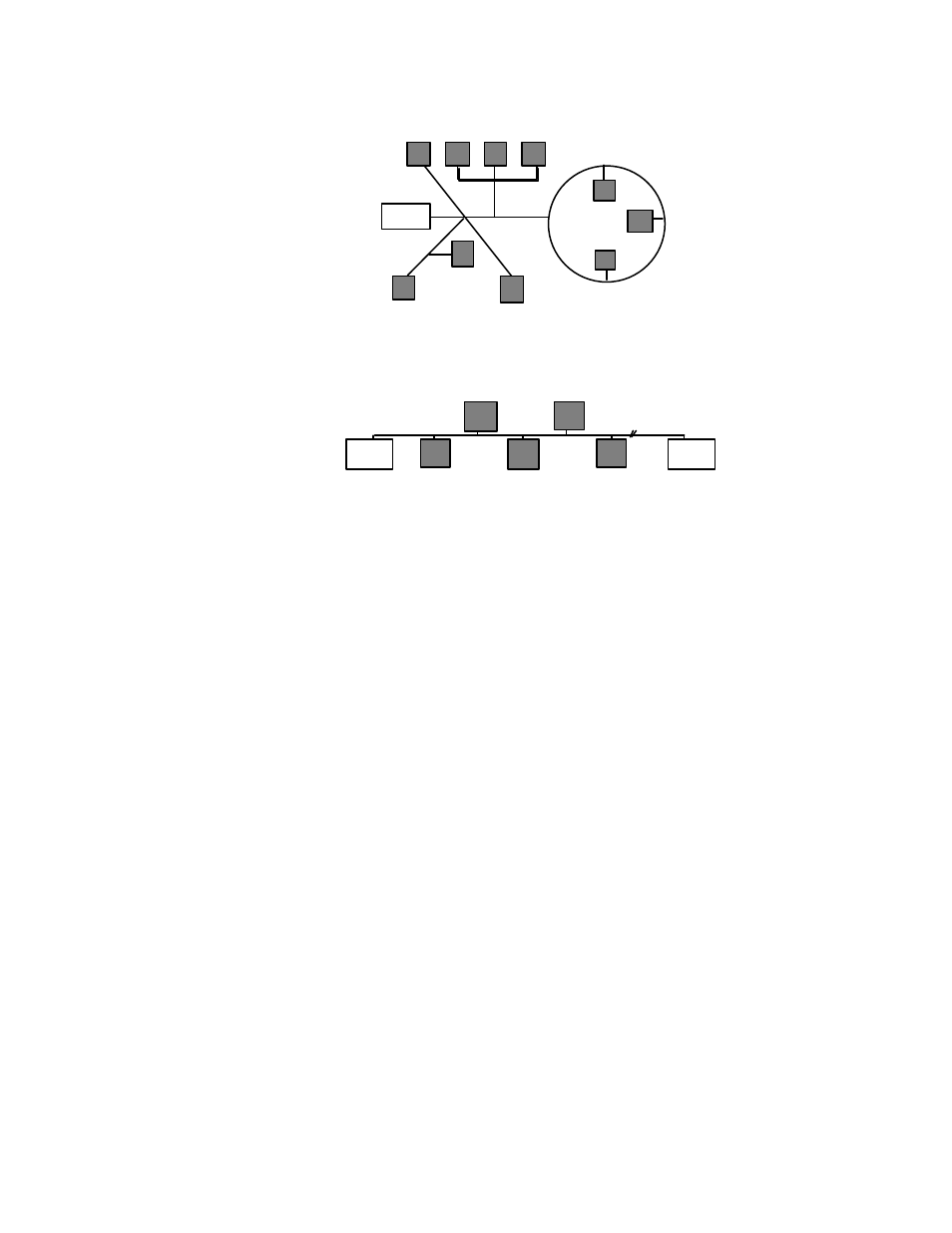
Termination
Figure 3.4 Mixed Topology (Model 44100 Terminator)
Termination
Termination
Figure 3.5 Doubly Terminated Bus Topology - Used for Very Long Cabling Distances
(Two Model 44101 Terminators)
A network consisting of LonPoint modules using the FTT-10A transceiver is said to
reside on a “TP/FT-10 channel.” In some cases all of the LonPoint modules will be
connected to a single TP/FT-10 channel. A maximum of 64 devices (LonPoint
modules, routers, PCLTA-10 and PCC-10 PC adapters, third-party L
ON
M
ARK
®
devices) may be connected to any one channel. If more than 64 devices are to be
used, or if it is necessary to add more cabling than is permitted on a single channel,
then one or more model 42100 LPR-10 Routers (TP/FT-10 to TP/FT-10) would be
placed in series with the network cabling.
Another application for the LPR Router is to limit the amount of network
communications passing between different parts of a control network. For example,
LPR Routers can restrict the transfer of messages from a portion of the network
with many active PID loops to other, more quiescent parts of the network. In this
case one or more model 42100 LPR-10 Routers would be placed in series with the
network cabling.
The LPR Router can also be used to create a high-speed backbone that brings
together many different channels, perhaps to a monitoring PC. In this case it may
be desirable to increase the speed of the backbone channel in order to better manage
the communication traffic. For example, in a highrise building it might be desirable
to have a78 kilobit per second TP/FT-10 free topology channel operating on each
floor, and use a 1.25 megabit per second channel to link together all of the floor
channels with a PC in the basement. In this case, one model 42102 LPR-12 Router
(TP/FT-10 to TP/XF-1250) would be placed on each floor and a separate 1.25Mbps
twisted pair channel would serve as a backbone.