Connecting wiring – Echelon LonPoint Module User Manual
Page 48
4-12
Installation and Wiring of Base Plates
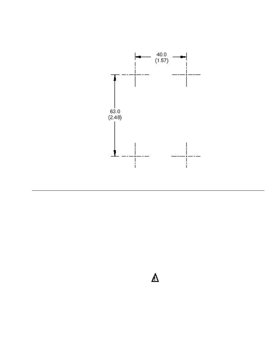
Figure 4.11 Mounting Holde Pattern Dimensions for Type1D Base Plates
Connecting Wiring
Route all network, power, and input/output cabling to the pertinent screw terminals
located at the top and bottom of the Base Plate. It is good practice to separate the
input/output cabling as much as possible from the network and power cabling,
especially if low-level analog signals are being supervised.
Strip the cable jacket and wire conductors. The base plate screw terminals will
accept 24AWG (0.5mm) to 12AWG(2.2mm) wire, which should be stripped to a
length of 0.32" (8mm). Although not required, it may be useful to use a soldering
iron to tin the stripped lengths of any strand wired to prevent fraying and
inadvertent contact with adjacent terminals. Identifying screw terminal numbers
are conveniently located both above and below each screw terminal. Symbols and/or
language identifying the function of the screw terminals also are provided.
Note that terminals 1 and 9 are numbered from left to right, but terminals 10 to 18
are numbered from right to left.
The optimum tightening torque for the screw terminals is approximately 4 pounds
(0.5Nm). The ideal flathead screwdriver tip width is 3/32" (2.5mm).