Lonpoint hardware guide 4-15, Jumper plugs (x-ray view), Type 2d type 1d type 1d – Echelon LonPoint Module User Manual
Page 51
LonPoint Hardware Guide
4-15
1 2 3 4 5 6 7 8 9
1
8
1
7
1
6
1
5
1
4
1
3
1
2
1
1
1
0
1
8
1
7
1
6
1
5
1
4
1
3
1
2
1
1
1
0
1 2 3 4 5 6 7 8 9
1
8
1
7
1
6
1
5
1
4
1
3
1
2
1
1
1
0
1 2 3 4 5 6 7 8 9
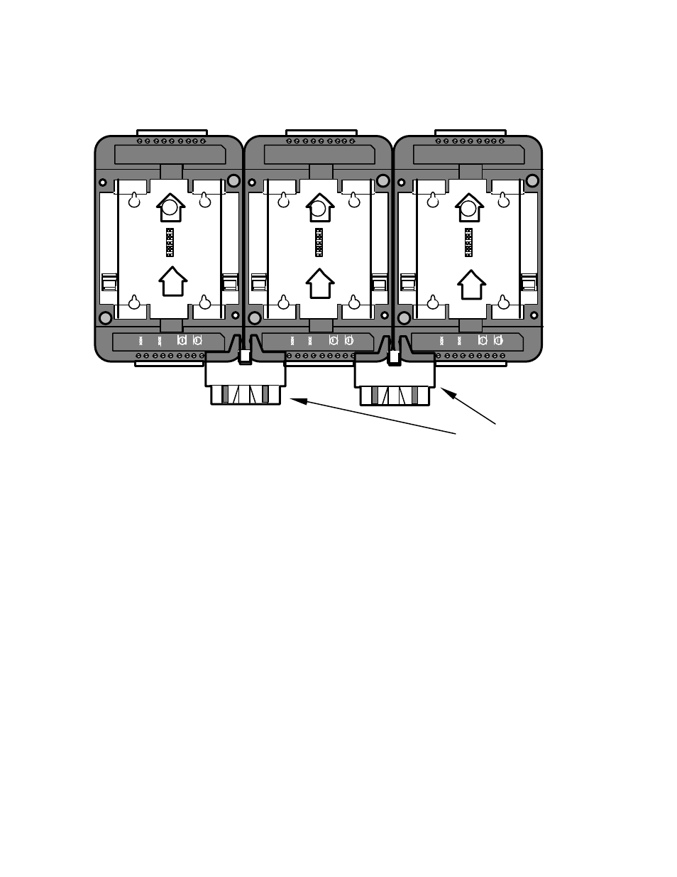
Jumper Plugs (x-ray view)
2
1A
1A
Type 2D
Type 1D
Type 1D
Figure 4.14 Mixing Type 1D and Type 2D Base Plates
The reason for this limitation is that only the right Jumper Plug connector on a
Type 2D Base Plate bridges the network connection; the left Jumper Plug connector
on a Type 2D Base Plate bridges only the power connection. This arrangement
permits several routers, each with a different channel type, to be mounted on a
common DIN rail and share a common power supply. Figure 4.15 shows mounting
configurations that are problematic and must be avoided because the router will
be unable to communicate with the other LonPoint modules via the Jumper Plug.
If such a mounting arrangement must tbe used, then the base plates must be
interconnected using wiring instead of the Jumper Plug.