Di-10 module software settings, Installing the di-10 module – Echelon LonPoint Module User Manual
Page 72
5-4
Installing the DI-10 Digital Input Module
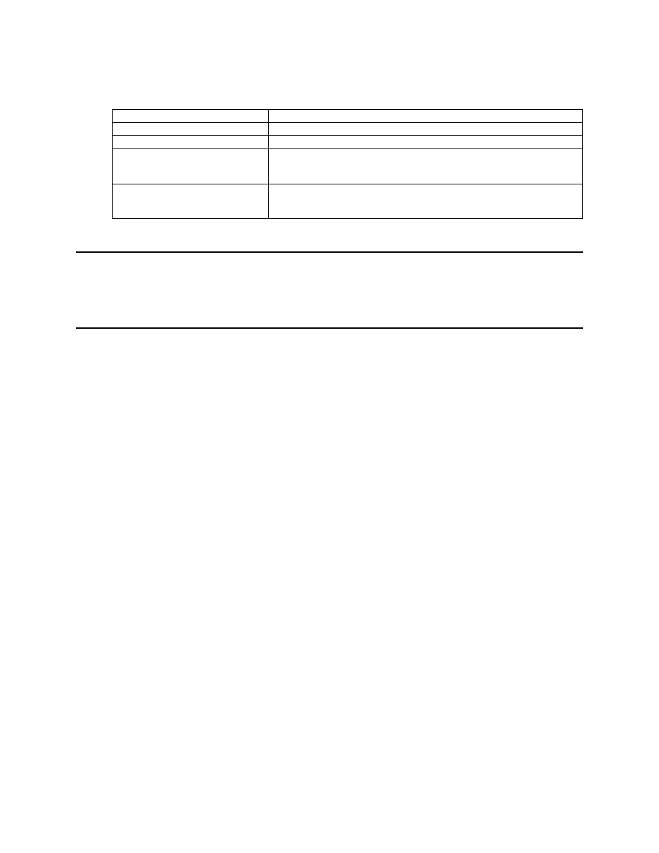
Humidity
10 to 95% RH @ 50°C
EMI
FCC A, CE Mark
Safety agency
UL 916
Function Blocks
Node object (1), digital input open-loop sensor objects (4),
digital encoder controller objects (2), analog function block
controller objects (4), type translators (6)
Software Configuration
Wide variety of L
ON
M
ARK
Standard Configuration Parameter
Types supported by direct memory read/write function of LNS
compatible network management tools
DI-10 Module Software Settings
The software settings of the DI-10 module are described in the LonPoint Application
and Plug-In Guide.
Installing the DI-10 Module
Installation of the DI-10 module involves the following steps:
1. Ensure that the Type 1 or Type 1D Base Plate has been wired and installed
correctly.
2. Check for continuity on all network and power wiring. Ensure that the correct
sensors are connected to the correct Base Plate I/O terminals.
3. Make certain that all network channels are terminated with the correct number
and type of Terminator.
4. Insert the DI-10 module into the Base Plate by aligning the network access jack
on the DI-10 with the arrow head on the Base Plate (the arrow should point in
the direction of the jack), and then pressing firmly to ensure that the module is
properly seated in its mating Base Plate connector.
5. The DI-10 module can be hot-plugged: there is no need to disconnect power
when installing the module. If power is present then the Power LED will
illuminate continuously. If power is not present then the Power LED will remain
off.
6. Securely attach the DI-10 module to the Base Plate by screwing the two Echelon
205-0130-01 screws (8-32 [M8], 3/8” [9.5mm]) into the threaded inserts in the
Base Plate. Use approximately 4 lbs. in. (0.5Nm) torque on the screws.
7. Follow the node configuration procedure described in the LonPoint Application
and Plug-In Guide
to configure the software in the DI-10 module.
8. See Troubleshooting for assistance with improper DI-10 module operation.