Lonpoint ai-10 analog input module, 2 installing the ai-10 analog input module, Ai-10 – Echelon LonPoint Module User Manual
Page 86
8-2
Installing the AI-10 Analog Input Module
LonPoint AI-10 Analog Input Module
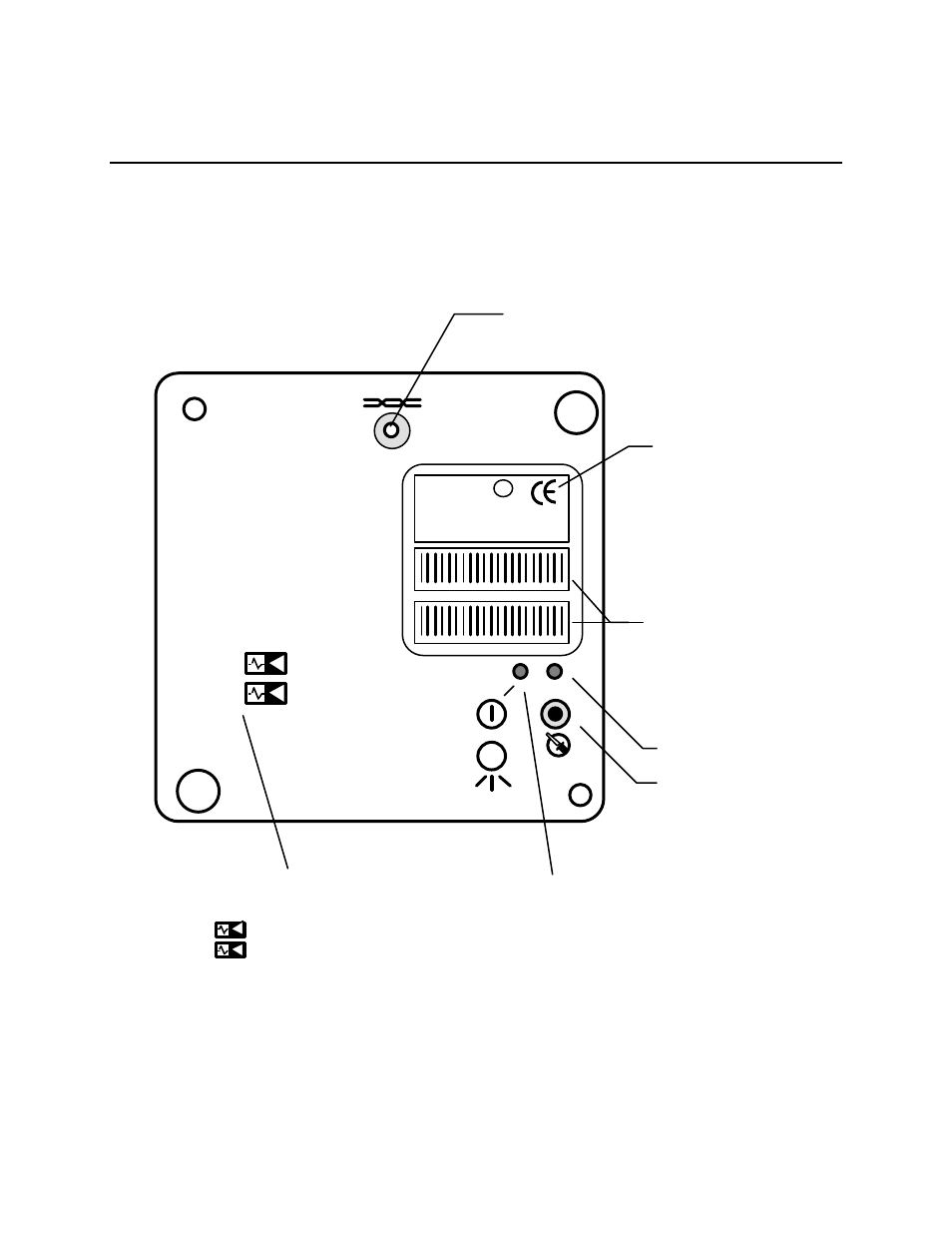
The front panel of the AI-10 module is shown in figure 8.1. There are no front panel
LEDs associated with the inputs, however, there are user-configured jumper blocks
that must be set correctly for each analog input.
Lo
nP
oi
nt
™
In
te
rfa
ce
Network Access Jack; Use
With Echelon PCC-10 Cable
Model 78303
Peel-Off Code 39
Format Bar Code of
LonPoint Interface
Neuron Chip ID
Number
LonPoint Interface
Model and Software
Revision
Service LED
Service Switch
Power/Wink LED:
Power ON: Illuminated Continuously
Wink: Flashing
Analog Input 1
Analog Input 2
Analog Input Identifier
(No LEDs For Analog Inputs)
1
AI-10
MODEL 41300 9760
SW VERSION 3.0
ID NUMBER
INPUT: 0-20VDC, 0-24mA EACH
LISTED 178K
ENERGY MANAGEMENT
EQUIPMENT SUBASSEMBLY
AI-10 MODEL 41300 ID NUMBER
AI-10 MODEL 41300 ID NUMBER
1
2
2
E
c
us
m
L
U
®
Figure 8.1 LonPoint AI-10 Analog Input Module - Front Panel