Echelon LonPoint Module User Manual
Page 32
3-10
Network Cabling and Connections
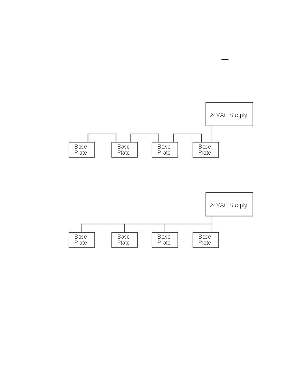
shown in figure 3.14. If >16 Amperes (>10 Amperes RMS at 24 VAC RMS for Type
1D/2D DIN Base Plates using Jumper Plugs) must be supplied then the loop-
through capability of the LonPoint Base Plate power terminals must not be used and
the power cabling should be run in parallel, as shown in figure 3.15. To calculate
the load current, divide the total VA (sum of all devices powered by the power
supply) by the power supply voltage. For example, if the total VA of all LonPoint
Modules and sensors/actuators equals 100VA, and the power supply provides 24
VAC, then the load current is 4.16A.
Figure 3.14 Looped-through Power Wiring - •16 Amperes at 24VAC for Type 1/2 Base
Plates, •10 Amperes for Type 1D/2D DIN Base Plates using Jumper Plugs
Figure 3.15 Parallel Power Wiring - >16 Amperes at 24VAC for Type 1/2 Base Plates,
•10 Amperes for Type 1D/2D DIN Base Plates using Jumper Plugs
As a rule of thumb, it is recommended that power and I/O cabling be separated by
18”/ 46cm to prevent inadvertent pick-up of noise from the power circuit by sensitive
analog I/O cabling. Power and network twisted pairs may be combined in a common
cable if using an approved network cable.
Depending on the model, the LonPoint modules require between 2 and 6.5VA at an
operating voltage of 16 to 30V DC or AC. The LonPoint Type 1/1D and Type 2/2D
Base Plates include a power-looping capability that provides continuity through the
Base Plate - even if the LonPoint module is removed - when the power cabling is
daisy-chained through each Base Plate.