Echelon LonPoint Module User Manual
Page 103
LonPoint Hardware Guide
10-3
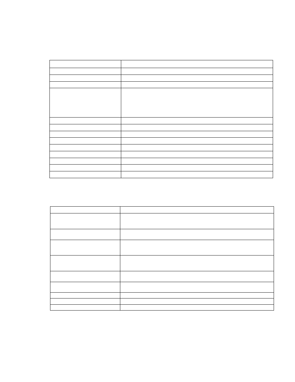
Table 10.1 SCH-10 Scheduler Module Wiring Connections
Screw Terminal
Wiring Connection
1 and 2
Incoming network wiring, TP/FT-10 channel, polarity-insensitive
3 and 4
Outgoing network wiring, TP/FT-10 channel, polarity-insensitive
5
Unused
6 and 7
Incoming power wiring, 16-30VAC or VDC, 2.4VA, polarity-
insensitive. If using DC power, it is good practice to maintain
continuity of the power polarity throughout the network. Terminals 6
and 8 should be the same polarity, and terminals 7 and 9 should be
the same polarity.
10
TXD
11
GND
12
RXD
13
GND
14
Unused
15
RTS
16
GND
17
CTS
18
GND
Table 10.2 LonPoint SCH-10 Scheduler Module Specifications
Function
Description
Processor/memory
Neuron 3150 Chip, 10MHz, 56K flash memory, 512K battery-
backed RAM (2 weeks minimum back-up, 5 months typical;
low-battery detection)
Clock/calendar
Battery-backed clock/calendar (10 year life, low-battery
detection), seconds, minutes, hours, day of week, month, year
Service function
Recessed service switch, service LED, power/wink LED. Dual
tear-off bar-code Neuron ID self-adhesive tags for application
to red-line drawings in the field
I/O — Not Currently
Supported — Reserved for
Future Use
EIA-232 serial port with software UART, selectable bit rate
(600, 1200, 2400, 4800), two start, one stop, and no parity bits.
Designed to support Termiflex or equal terminal
I/O isolation
100V, transformer isolation. Outputs are isolated from the
input power and the network but not from each other.
Transceiver type
FTT-10A with blocking capacitors for compatibility with link
power channel
Network connector
Phone plug connector accessible from front panel
Input power
16-30VAC or VDC @ 2.4VA, internally isolated power supply
Mounting
Type 1 or Type 1D Base Plate