Connecting the jumper plug(s) – Echelon LonPoint Module User Manual
Page 49
LonPoint Hardware Guide
4-13
Table 4.2 Type 1D Base Plate Terminal Block Connections
Terminal Number
Function
1 -4
Network
5
Cable shield, if used
6 - 9
Power
10 - 18
I/O
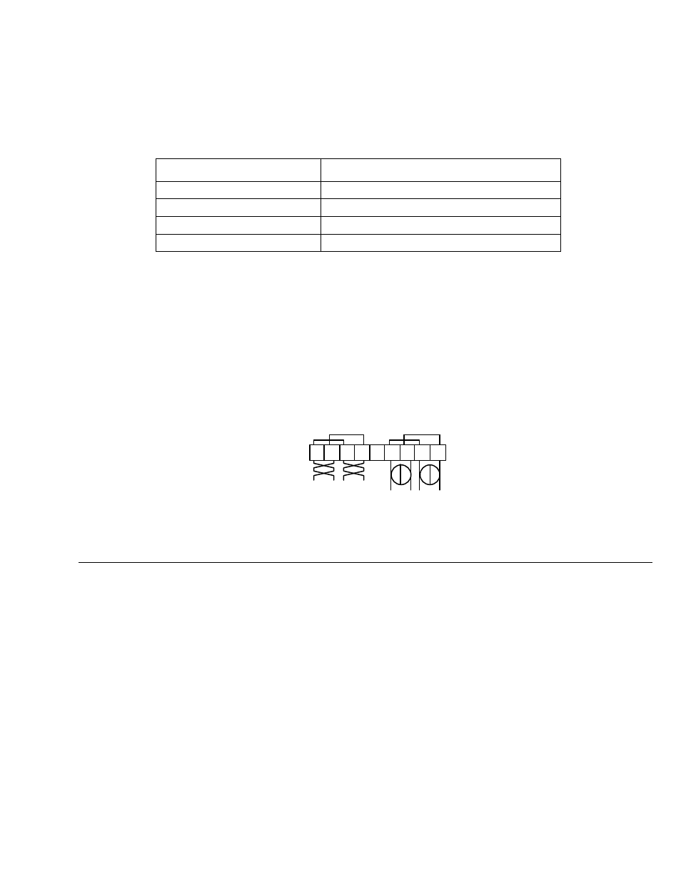
Two sets of screws are provided for both the power and network wiring connections.
These connections are internally jumpered on the Type 1D Base Plate PCB to
provide continuity of the network and power wiring, even if no LonPoint module is
installed, as shown in figure 4.12. This feature permits the base plate wiring to be
pre-installed and the network and power circuits checked for continuitiy throughout
the installation, before a single LonPoint module is ever installed. This feature also
prevents network and power interruptions as a result of hot swapping LonPoint
modules during commissioning or service operations. Finally, providing two sets of
screw terminals permits incoming and outgoing wiritng to be landed at separate
screw terminals without the need to insert more than one wire in any given screw
terminal.
1 2 3 4 5 6 7 8 9
Network
16-30VAC or VDC
Figure 4.12 Base Plate Power and Network Wiring Connections
Connecting the Jumper Plug(s)
From time to time it may be necessary to mount two or more LonPoint Type 1D or
2D Base Plates adjacent to one another. In these instances, power and network
wiring must be daisy-chained between each Base Plate. Routing power and network
wiring between multiple base plates can be a laborious and time consuming task,
and there is always the risk of a wiring error. For this reason, the Type 1D and 2D
Base Plates are each supplied with a Jumper Plug and Jumper Plug connecotrs
which simply and easily bus the power and network between adjacent Base Plates.
The Jumper Plug connectors are located on either side of the terminal block with
connections 1 to 9 . The Jumper Plug connectors are wired in parallel with the
network and power connections on the screw terminals. When two Base Plates are
mounted adjacent to each other, with the mounting arrows pointing in the same
direction, the Jumper Plug connectors will be aligned such that a Jumper Plug may
be inserted into the two connectors, thus bridging power and network between the
two Base Plates (figure 4.13).