AMT Datasouth 41AY89AR777 User Manual
Page 57
Attention! The text in this document has been recognized automatically. To view the original document, you can use the "Original mode".
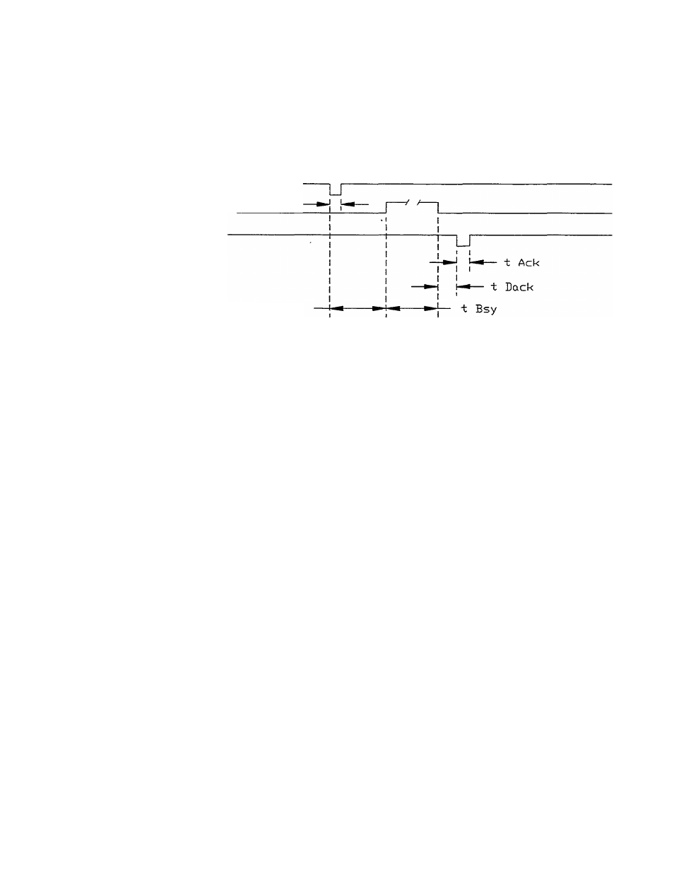
Figure 3.4 shows the tuning diagram for the printer.
Data Lines <8)
/ / / / \
Data
Strobe
Busy
Ack
t BDLY
BDLY:
nin. =
max. =
250
400
ns
ns
BSY:
nin. =
nax. =
100
4
¡xs
sec
ACK:
=
3
¡xs
BACK:
nax, =
20 ns
Figure 3.4 Parallel Data Timing (upwards Centronics Compatible)
Along with different interpretations of the Centronics Specifications, parallel
interface connectors also have different connector pin assignment conventions.
For example, pin 11 may not always be assigned Busy. Because of such
variations, it may be necessary to connect the interface on a pin-by-pin basis.
The technician must compare the connector-pin assignments of the host to those
of the printer and make certain die interface is made by connector-pin assignment
and not by pin number. The connector-pin assignment configuration for the
printer parallel interface is given in Table 3.2.
If it is necessary to construct an interface cable, the length of the cable should not
exceed 10 feet. On the printer end of the cable use a micro ribbon coimector, part
no. 57-30360 for round cable or part no. 57F-30360 for flat cable.
3-6