General, Remote panel cables, Description – Generac Power Systems NP-40G User Manual
Page 98: Wiring connections, Owiring connections
Attention! The text in this document has been recognized automatically. To view the original document, you can use the "Original mode".
Section 6.6- OPTIONAL REMOTE PANEL
General
An optional remote-mounted Start-Stop panel is
available. This panel will permit the generator to be
started and stopped from some convenient remote
location In the recreational vehicle.
Remote Panel Cables
The generator Is equipped with a 4-pin receptacle
for connection of the remote panel. Cables are
available which mate with the receptacle and Inter
connect the generator with the remote panel.
□ Cable Model 9045 is a 10 foot long, 4-wlre cable.
□ Cable Model 9046 Is a 30 foot long, 4-wire cable.
Figure 1. Remote Panel Receptacle
WIRE #18
(STOP)
WIRE #14
(ENGINE RUN SIGNAL)
WIRE #0
(GROUND)
WIRE #17
(CRANK)
Description
MODEL 9042:
The Model 9042 remote panel mounts a rocker
type Start-Run-Stop switch and a "GEN. RUN" ad
visory lamp. The lamp Is turned on by Wire 14
current when the generator Is running.
Figure 2. Model 9042 Remote Panel
J
MODEL 9043:
The Model 9043 remote panel mounts a rocker
type Start-Run-Stop switch, a "GEN. RUN" lamp
and an hourmeter.
The "GEN. RUN" lamp will turn on when the
engine Is running. It is turned on by Wire 14 power.
The Hourmeter provides a continuous Indication
of oenerator operating hours in hours and tenths
of hours. It can be used in conjunction with the
required periodic maintenance on the unit.
Figure 3. Model 9043 Remote Panel
^GENERAC R.V. GENERATOR °
o
GEN.
RUN
STOP
START
O
TOTAL HOURS
o
o
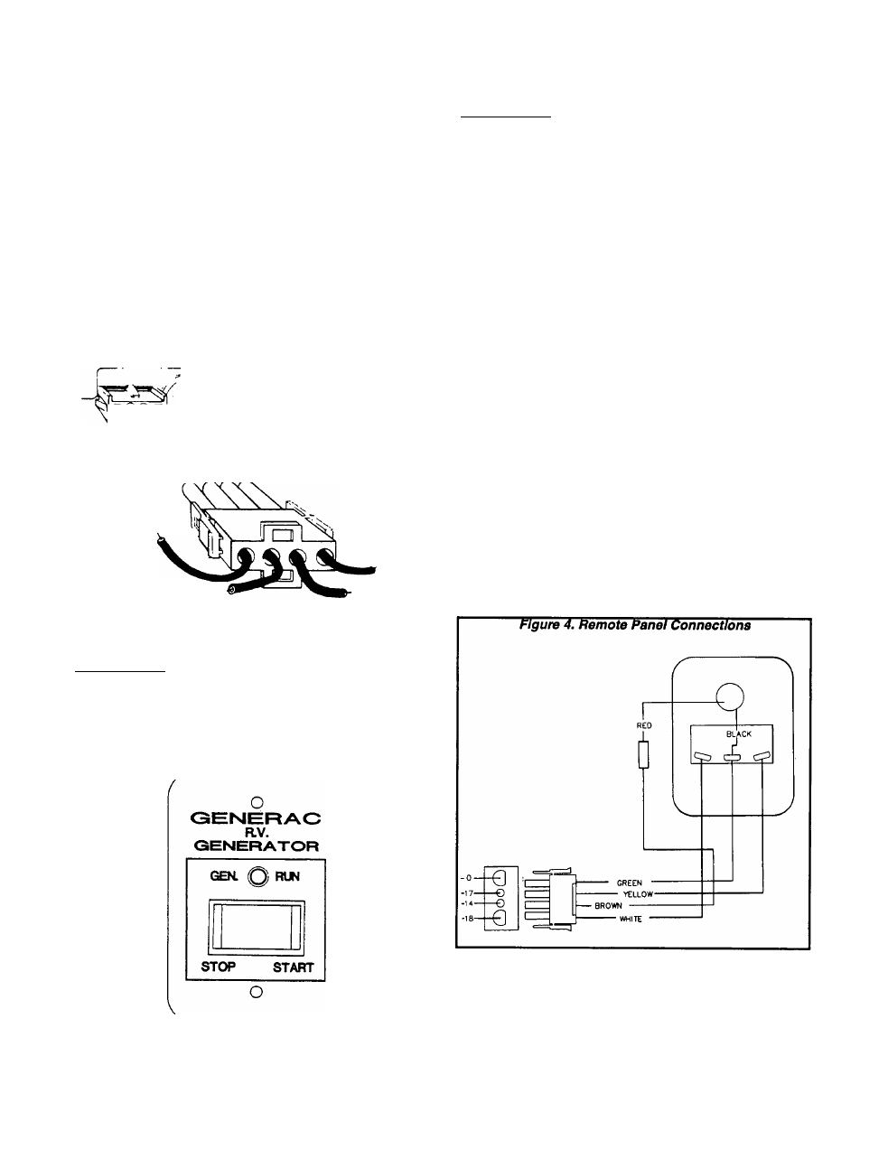
Wiring Connections
wiring connections for the remote panel are
shown in Figure 4.
Page 6.6-1