Introduction, Ignition cage assembly, Ignition sensor – Generac Power Systems NP-40G User Manual
Page 92: Ignition moduie
Attention! The text in this document has been recognized automatically. To view the original document, you can use the "Original mode".
Section 6.4- ENGINE IGNITION SYSTEM
Introduction
The engine ignition system consists of the fol*
lowing major components:
□ Ignition Cage Assembly.
□ Ignition Sensor Assembly.
□ Ignition Module (IM).
□ Ignition Coll (1C).
□ Spark Plug (SP1).
Ignition Cage Assembly
An IGNITION CAGE ASSEMBLY is factory In
stalled onto the permanent magnet rotor hub. Two
magnets are installed In the cage as shown In
Figure 1 (50* apart), so that the north pole of one
magnet faces away from the cage outer periphery
and the north pole of the other mag net faces toward
the cage outer periphery. A special fixture Is used
to install the cage onto the rotor hub so that the
center line of the first magnet Is 68* away from the
Rotor Hub mounting hole as shown.
NOTE: Placement of the magnets on the Rotor Hub
at the exact position stated above results In an
Ignition timing of 29’ BTDC.
The Ignition Cage assembly cannot be replaced.
The entire Rotor Hub must be replaced.
Replacement Rotor Hubs will include a factory
installed Ignition Cage assembly, and Magnetic
Housing Assembly.
NOTE: Also refer to “Permanent Magnet Rotor" In
Section 1^ (Page 1.2-1).
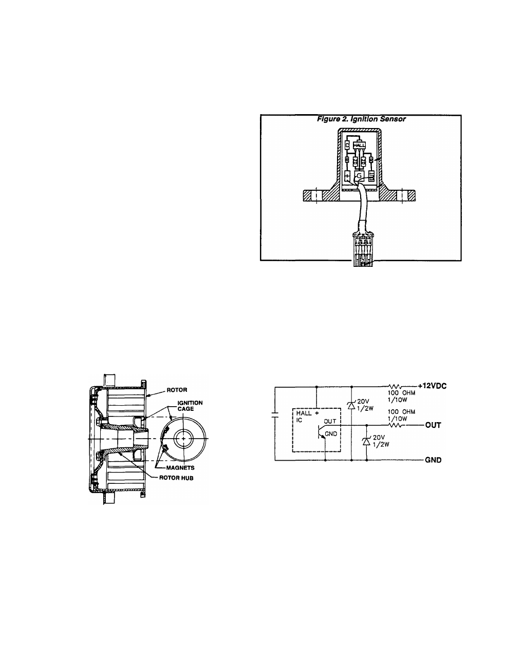
Figure 1. Ignition Cage Assembly
Ignition Sensor
The Ignition Sensor is retained to the AC
e
enerator’s Stator Adapter by means of two M4-
.70 X 8mm screws and lockwashers. The Sensor
housing houses a circuit board. The entire housing
cavity is filled with potting material.
As the generator’s Permanent Magnet Rotor
turns during operation, magnets on the Ignition
Cage rotate past the Ignition Sensor to induce a
timed low voltage pulse Into the Sensor. This volt
age pulse Is delivered to an Ignition Module and
serves as a timing pulse for the Module.
See Figure 3. The Sensor circuit board mounts
solid state components which are sensitive to mag
netism. Magnets In the Ignition Cage rotate past the
Sensor, causing the base of a transistor to be
"pulsed". The transistor acts much like a "switch"
or a set of "contact points". Pulsing the transistor
base causes the "switch" to close and connect the
"OUT" lead to the "GND" lead. This triggers the
Ignition Module to delivers primary Ignition current
to the Ignition Coll at timed Intervals.
Figure 3. Ignition Sensor Schematic
ignition Moduie
While cranking and running, battery voltage Is
delivered to the Ignition Module via Wire 14 from
the Engine Controller circuit board. The Module will
deliver this battery voltage to the Ignition Coll
based on the "timing" signal it receives from the
Ignition Sensor.
The Ignition Module Is retained In the generator
control panel by two capscrews.
Page 6.4-1