General information, Description, Carburetor disassembiy – Generac Power Systems NP-40G User Manual
Page 59
Attention! The text in this document has been recognized automatically. To view the original document, you can use the "Original mode".
Section 3.4- CARBURETOR
General Information
Proper engine performance depends on the car-
buretion system. The use of clean, fresh gasoline
and a well-maintained air cleaner are extremely
important to proper operation, as well as engine
reliability and power.
Most causes of carburetion problems are related
to the use of stale, gummy fuel and the Ingestion
of dirt Before servicing the carburetor, be sure to
check for evidence of these conditions. Gasoline
that is left in the fuel lines for long periods can form
gum or varnish deposits that will adversely affect
carburetor operation.
NOTE:
A
commercial
fuel
stabilizer
(such
as
STABIL®) will minimize the formation of gum de
posits
durina
storage.
Add
the
stabilizer
to
the
gasoline In the fuel tank or In the storage container,
hollow
the
ratio
recommended
on
the
stabilizer
container. Run the engine for about 10 minutes
after adding stabilizer, to allow It to enter the car
buretor. "S
t
ABIL®“ I
s
a brand name fuel stabilizer
that can be purchased In most automotive repair
facilities or In lawn and garden centers.
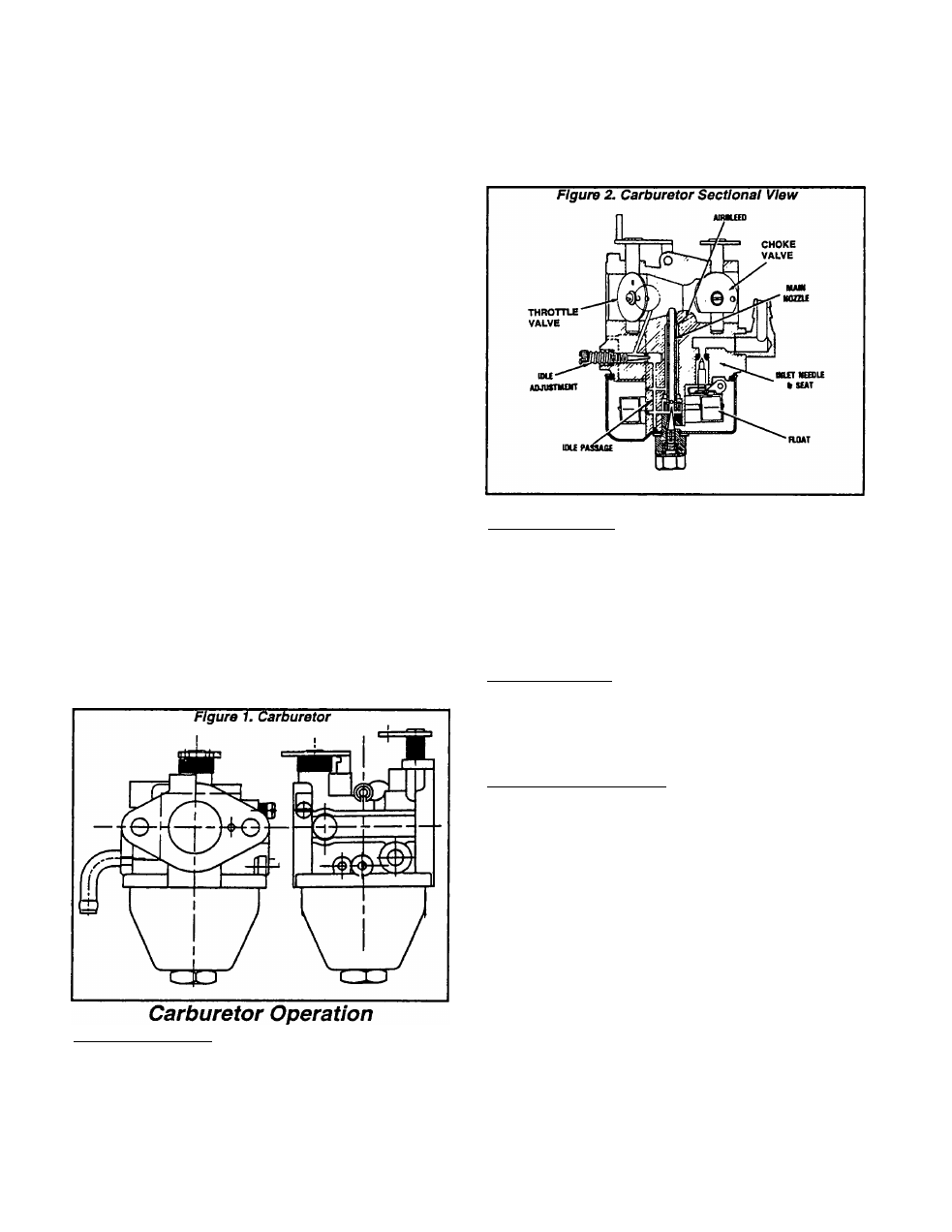
Description
The carburetor used on GN-190 and GN-220 en
gines is a float type with fixed main jet. Carburetor
throttle position and engine speed are controlled
by an electric stepper motor. The stepper motor
moves the throttle in response to signals received
from a CCG circuit board. The circuit board senses
load voltage, establishes the correct engine speed
to obtain correct voltage and delivers an output
signal to the stepper motor. The stepper motor
adjusts the engine throttle to change engine speed
and establish correct output voltage.
FLOAT OPERATION;
A hollow plastic float maintains fuel level In the
float bowl. As fuel is used, the float moves down
ward to move an inlet needle valve off its seat.
When the needle valve moves off Its seat, fuel
can flow Into the bowl. As the fuel level rises, the
float moves upward to force the needle valve
against its seat and stop the flow into the bowl.
CHOKE POSITION:
The choke valve is closed to restrict the flow of
air Into the engine. As the engine cranks, air pres
sure in the cylinder is reduced. Since the air intake
passage is partially blocked by the choke valve,
fuel is drawn from the main nozzle and from the idle
discharge port. This creates the very rich fuel mix
ture required for starting a cold engine.
IDLE OPERATION:
The throttle valve is nearly closed to shut off the
fuel supply from all ports except the primary Idle
fuel discharge port. Engine suction then draws
fuel only from that port.
HIGH SPEED OPERATION;
The throttle valve is wide open. This allows a
large volume of air to pass through the carburetor
at a high velocity. The high velocity air flow past
the carburetor venturi results in a drop In air pres
sure at the venturi throat This reduceo air pressure
draws fuel through the main nozzle that opens into
the venturi which then mixes with the air in the air
passage.
Carburetor Disassembiy
See Figure 3, next page. The carburetor can be
disassembled as follows:
1. Remove the BOWL NUT (Item 3) and the FIBER
WASHER (Item 4). Then, remove the FLOAT BOWL
(Item 5).
2. Remove the FLOAT PIN (Item 6). Then, remove
the FLOAT (Item 7) and the INLET VALVE (Item 8).
Page 3.4-1