Generac Power Systems NP-40G User Manual
Page 94
Attention! The text in this document has been recognized automatically. To view the original document, you can use the "Original mode".
________________ Section 6.4- ENGINE IGNITION SYSTEM
TESTING FOR SPARK:
To test the Ignition system, a suitable spark tes
ter may be used. Such spark testers are commer
cially available. Test the system as follows:
1. Disconnect the high tension lead from the spark
plug.
2. Attach the spark plug
high tension lead to the
spark tester terminal.
3. Connect the spark tester
clamp to the engine cylin
der head.
4. Crank the engine rapidly.
Engine must be turning at
350 rpm or more. If spark
Jumps the tester gap, you
may assume the ignition
system is operating satis
factorily.
If sparking across the tester gap does-NOT
occur, go to XHECK POWER SUPPLY".
CHECKING ENGINE MISS:
To determine if an engine miss is Ignition related,
connect the spark tester In series with the spark
plug’s high tension lead and the spark plug. Then,
start the engine. If spark jumps the tester gap at
regular intervals but the engine miss continues, the
problem is In the spark plug or in the fuel system.
CHECK POWER SUPPLY:
When the engine is being cranked, battery volt
age should be available from the Engine Controller
circuit board to a 4-termlnal connector via Wire 14.
From the 4-termlnal connector, battery voltage
should be available to the Ignition Module via Wire
14 (RED wire). And battery voltage should be avail
able from the Ignition Module to the Ignition Sensor
via a RED wire. If this 12 VDC power supply is not
available, the ignition system will not function. To
check the power supply, proceed as follows using
a volt-ohm-milliammeter (VOM):
1. Gain access to the control panel interior.
2. In the panel, locate the 3-pin connector that
Interconnects the Ignition Module and the ignition
Sensor.
3. Press down on the connector lock tang and
disconnect the two connector halves.
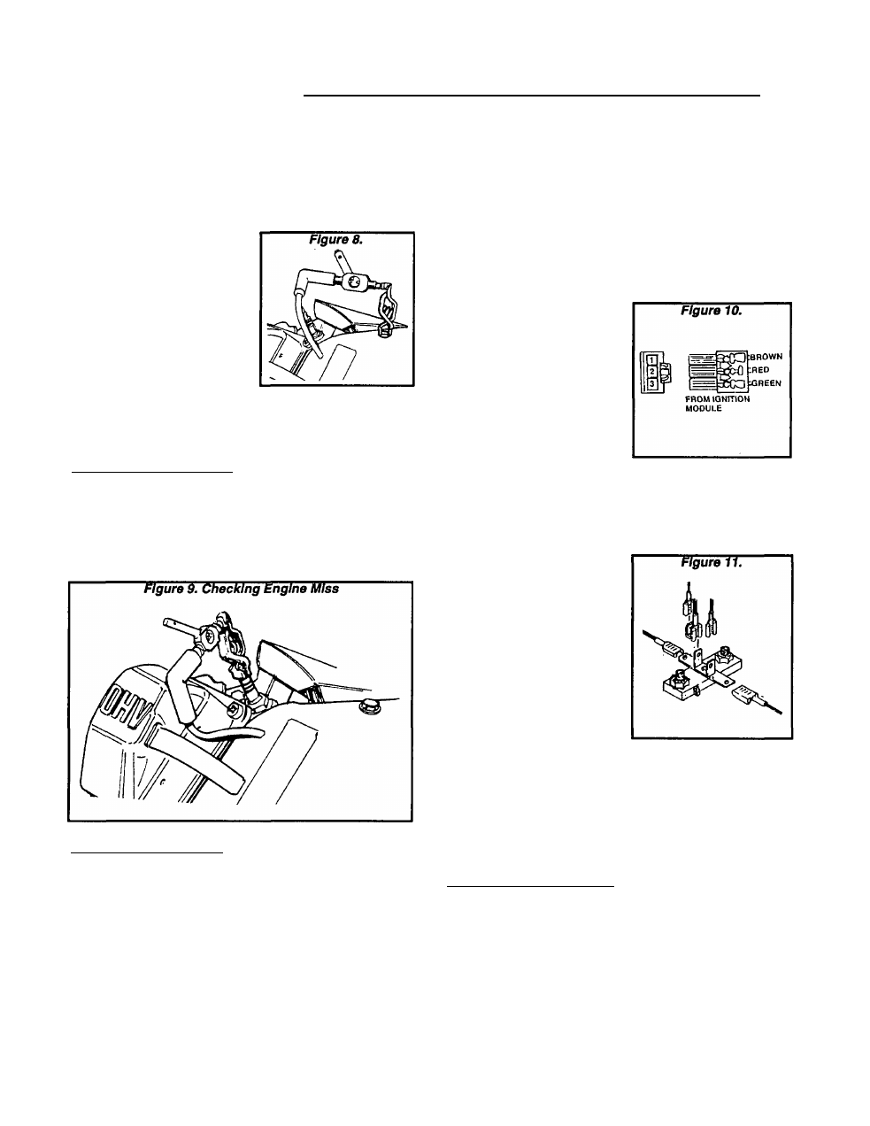
NOTE: A single large black lead carries the three
leads from the Ignition Sensor to the 3-pln MALE
connector. The three leads from the Ignition Mod
ule (brown, green and red) attach to the 3-pln FE
MALE connector.
4. Set the VOM to a scale
that will allow battery volt
age to be read (about 12
volts DC).
5. Connect the meter test
leads across the center FE
MALE pin (RED wire) and
frame ground.
6. Hold the Start-Run-Stop
switch at "START". The
meter should read battery
voltage.
If battery voltage Is NOT indicated, go to Step 7.
If battery voltage IS Indicated, go to "CHECK IGNI
TION SENSOR^..
7. Now locate the 4-termi
nal connector in the panel.
Connect the VOM test
leads across the terminal
and frame ground. Crank
the engine and the VOM
should read battery volt
age.
a. If battery voltage is
indicated now but was
NOT Indicated In Step 6,
test Wire 14 (RED) be
tween the 4-terminal
connector and the Igni
tion Module. If wire is
bad, repair or replace as necessary.
b. If battery voltage Is NOT Indicated In Step 7,
test Wire 14 between the 4-terminal connector
and the Engine Controller circuit board. Repair
or replace as necessary.
CHECK IGNITION SENSOR:
1. In the 3-pln connector plug half from the Ignition
Module, locate FEMALE Pin 1 to which the BROWN
wire connects.
2. Connect a jumper wire from FEMALE Pin 1
(BROWN wire) to frame ground.
3. Connect the Spark Plug high tension lead to a
spark tester (Figure 8) and the spark tester clamp
to ground.
Page 6.4-3