Battery (continued), Start-run-stop switch (sw1), Starter contactor – Generac Power Systems NP-40G User Manual
Page 89
Attention! The text in this document has been recognized automatically. To view the original document, you can use the "Original mode".
Section 6.3- ENGINE CRANKING SYSTEM
Battery (Continued)
TESTING A BATTERY (CONT’D);
If the battery State of Charge Is less than 100%,
use an automotive type battery charger to recharge
It to a 100% State of Charge.
2. Test for Condition:
a. If the difference In specific gravity between the
highest and lowest reading cell is greater than
0.050 (50 points), the battery is nearing the end
of Its userul life and should be replaced.
b. However, If the highest reading cell is less than
1.230, recharge thebattery and repeat the test.
Start-Run-Stop Switch (SW1)
Wires 17 and 18 connect
to the two outer terminals
of the switch. Wire 0
(ground) connects to the
switch center terminal.
The switch can be tested
using a volt-ohm-milliam-
meter (VOM) as follows:
1. Set the VOM to Its" Rxl “ scale and zero the meter.
2. Connect the VOM test leads across the Wire 17
terminal and the center (Wire 0) terminals.
a. Hold the switch at "START" and the VOM
should indicate "continuity".
b. Hold switch at "STOP" and meter should read
"infinity".
3. Now, connect the meter test leads across the
center and Wire 18 terminals.
a. With switch at “START" VOM should Indicate
"infinity".
b. With switch at "STOP", meter should read
"continuity".
Replace the switch If It is defective.
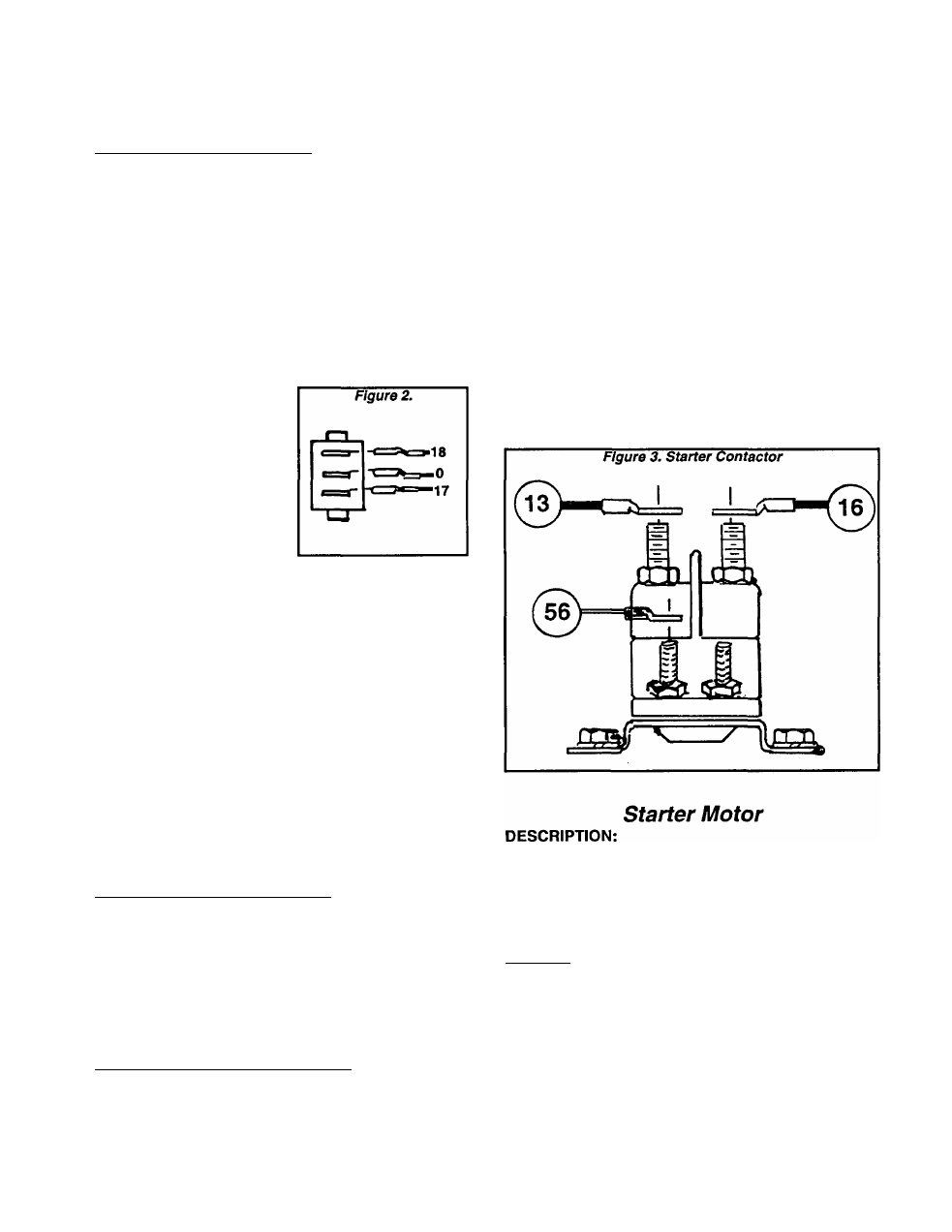
Starter Contactor
WIRE AND CABLE CONNECTIONS:
The red (positive) battery cable connects to one
of the starter contactor’s large terminal lugs. The
unit’s 15 amp fuse also attaches to this lug, via Wire
13.
The starter motor (SM) cable (16) attaches to the
second terminal lug.
Wire 56, from the engine controller circuit board,
attaches to one of the small contactor terminals.
TESTING THE STARTER CONTACTOR:
To test the installed Starter Contactor, proceed
as follows:
1. Set a volt-ohm-milliammeter (VOM) to read bat
tery voltage (12 VDC).
2. Connect the VOM test leads across the Wire 56
terminal of the Contactor and frame ground. The
meter should Indicate "zero" volts.
3. Hold the Start-Run-Stop switch at "START" and
the VOM should read battery voltage and the Con
tactor should energize. After reading the voltage,
release the switch. If battery voltage Is NOT indi
cated, a problem exists elsewehere in the circuit
4. Connect the VOM test leads across the Wire 16
terminal lug and frame ground.
a. Hold the Start-Run-Stop switch at “START".
The Contactor should actuate and the meter
should Indicate battery voltage.
b. If battery voltage Is not Indicated, replace the
Starter Contactor.
c. If battery voltage Is Indicated but engine does
not crank, check the Starter Motor and its cable.
The Starter Motor is a 12 volts negative ground
type. It Is capable of operating on heavy duty bat
tery Input at temperatures as low as -30 F. without
any significant change in performance. Its pinion
is a 10-tooth type having a 20’ pressure angle.
TESTING:
Connect the test leads of a VOM across the
Starter Motor terminal and case. Hold the Start-
Run-Stop switch at "START". The VOM should read
battery voltage and the Starter Motor should turn.
If VOM reads 12 volts DC and the Motor does not
turn, the Motor is probably defective. Remove the
Motor and test with a 12 volts DC power source.
Replace the Starter Motor if defective.
Page 6.3-2