Camshaft inspection (continued), Crankshaft inspection – Generac Power Systems NP-40G User Manual
Page 49
Attention! The text in this document has been recognized automatically. To view the original document, you can use the "Original mode".
Section 2.4- CRANKSHAFT AND CAMSHAFT
Camshaft Inspection (Continued)
The following should be measured carefully to check
for wear:
MAIN CAMSHAFT BEARING DIAMETER
(FLYWHEEL END)
DESIGN DIAMETER: 1.022-1.023 Inch (25.96-25.98mm)
WEAR LIMIT: 1.020 Inch (25.91mm) Minimum
MAIN CAMSHAFT BEARING DIAMETER
(PTO END) GN-190 ONLY
DESIGN DIAMCTER: 1.022-1.023 Inch (25.96-25.98mm)
WEAR LIMIT: 1.020 Inch (25.91mm) Minimum
MAIN CAMSHAFT BEARING DIAMETER
(PTO END) GN-220 ONLY
DESIGN DIAMETER: 1.297-1.298 Inch (32.96-32.98mm)
WEAR LIMIT: 1.295 Inch (32.89mm) Minimum
CAMSHAFT BEARING BORE IN CRANKCASE
DESIGN DIAMETER: 1.024-1.025 Inch (26.00-26.03mm)
WEAR LIMIT: 1.026 Inch (26.06mm) Maximum
CAMSHAFT BEARING BORE IN CRANKCASE COVER
DESIGN DIAMETER: 1.299-1.300 inch (33.00-33.03mm)
WEAR LIMIT: 1.302 Inch (33.06mm) Maximum
CAM LIFT
DESIGN LIFT: 0.210-0.212 Inch (5.34-5.38mm)
WEAR LIMIT: 0.206 Inch (5.24mm) Minimum
Crankshaft Inspection:
CRANKSHAFT PROPER:
Use a commercial solvent to clean the crankshaft.
After cleaning, Inspect the crankshaft as follows:
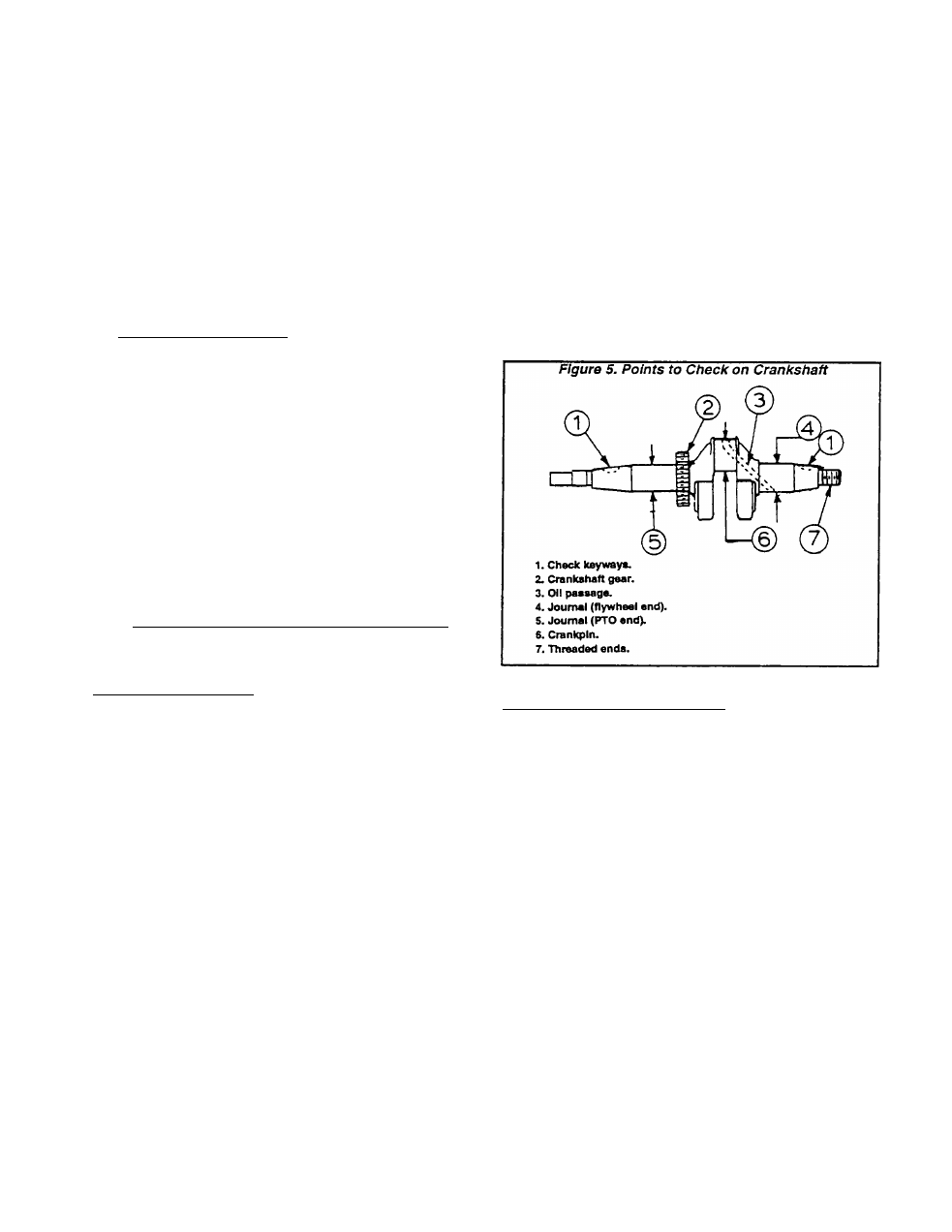
□ Inspect keyways in crankshaft, make sure they are
not worn or spread. Remove burrs from edges of
keyway, to prevent scratching the bearing.
D
Inspect timing gear teeth for chipping or cracking. If
the timing gear Is damaged, the crankshaft assembly
must be replaced.
G
Inspect the crankpin for damage, nicks, scratches,
etc. Small nicks and scratches may be polished out
using fine emery cloth. ALL EMERY RESIDUE MUST
BE REMOVED. Use a solvent (such as kerosene) to
remove emery residue.
D Carefully measure the outside diameter (O.D.) of the
crankpin, crankshaft journal at flywheel end, and
crankshaft journal at PTO end. Replace the crank
shaft if it is worn smaller than the stated limits.
NOTE: DO NOT regrInd the crankpin to any smaller
diameter. Undersize connecting rods are NOT
available for the GN-190 or GN-220 engines.
G
Inspect oil passage. Use a length of wire to make
sure it Is open. Inspect threaded ends of crankshaft.
CRANKPIN OUTSIDE DIAMETER
DESIGN DIAMETER: 1.180-1.181 INCH (29.99-30.01 MM)
WEAR LIMIT: 1.179 inch (29.96mm) Minimum
CRANKSHAFT BEARING JOURNAL (FLYWHEEL END)
DESIGN DIAMETER: 1.102-1.103 Inch (28.000-
28.012mm)
WEAR LIMIT: 1.100 inch (27.95mm) Minimum
CRANKSHAFT BEARING JOURNAL (PTO END)
DESIGN DIAMETER: 1.102-1.103 inch (28.000-
28.012mm)
WEAR LIMIT: 1.186 inch (27.95mm) Minimum
CRANKSHAFT SLEEVE BEARING:
A sleeve bearing (Figure 6) Is pressed into the crank
shaft bore of the crankcase. A bearing is NOT provided
for the crankshaft bore in the crankcase cover.
Inspect the sleeve bearing In the crankcase for dam
age. Measure the inside diameter (I.D.) of the sleeve
bearing. Replace any sleeve bearing that Is worn exces
sively. Press out the old bearing, press a new bearing
into place.
CRANKSHAFT SLEEVE BEARING
DESIGN DIAMETER: 1.104-1.106 inch (28.044-
28.099mm)
WEAR LIMIT: 1.107 inch (28.129mm) Maximum
Check the crankshaft bearing bore in the crankcase
cover. If limits are exceeded, replace the crankcase
cover.
CRANKSHAFT BEARING BORE IN CRANKCASE
COVER
DESIGN DIAMETER: 1.104-1.105 inch (28.040-
28.065mm)
WEAR LIMIT: 1.106 inch (28.092mm) Maximum
Page 2.4-2