Piston rings, Section 2,3- piston, rings, connecting rod, Piston (continued) – Generac Power Systems NP-40G User Manual
Page 45
Attention! The text in this document has been recognized automatically. To view the original document, you can use the "Original mode".
Piston Rings
Section 2,3- PISTON, RINGS, CONNECTING ROD
Piston (Continued)
CHECK PISTON FOR WEAR (CONT’D):
4. Check Wrist Pin for Wear:- Measure the outside diam
eter of the wrist pin. Also measure the inside diameter of
the wrist pin bore in the piston and In the connecting rod.
Also check wrist pin length. Replace any component that
is worn excessively.
GENERAL:
The following rules pertaining to piston rings must
always be complied with:
□
□
WRIST PIN OUTSIDE DIAMETER (GN190 & GN220)
DESIGN DIAMETER: 0.708-0.709 Inch (17.989-
18.000mm)
WEAR UMIT: 0.707 Inch (17.969mm) Minimum
WRIST PIN LENGTH (GN190 & GN220)
DESIGN LENGTH: 2.196-2.213 Inch (55.8-56.2mm)
WEAR LIMIT: 2.193 inch (55.7mm) Minimum
WRIST PIN BORE IN PISTON (GN190 & GN220)
DESIGN DIAMETER: 0.708-0.709 inch (18.000-
18.011mm)
WEAR LIMIT: 0.710 Inch (18.026mm) Maximum
CONNECTING ROD SMALL END I.D. (GN190 & GN220)
DESIGN DIAMETER: 0.709-0.710 inch (18.02-18.03mm)
WEAR UMIT: 0.711 inch (18.05mm) Maximum
5. Ring to Groove Side Clearance:- Clean carbon from
piston ring groov js. Install new rings. Use a feeler gauge
to measure the side clearance between the rings and ring
grooves. If ring-to-groove side clearance exceeds the
stated limits, replace the piston.
RING TO GROOVE SIDE CLEARANCE (GN190 &
GN220)
0.0004-0.0014 inch (0.012-0.034mm)
Figure 6. Ring to Groove Side Clearance
1ST COMPRESSION RING
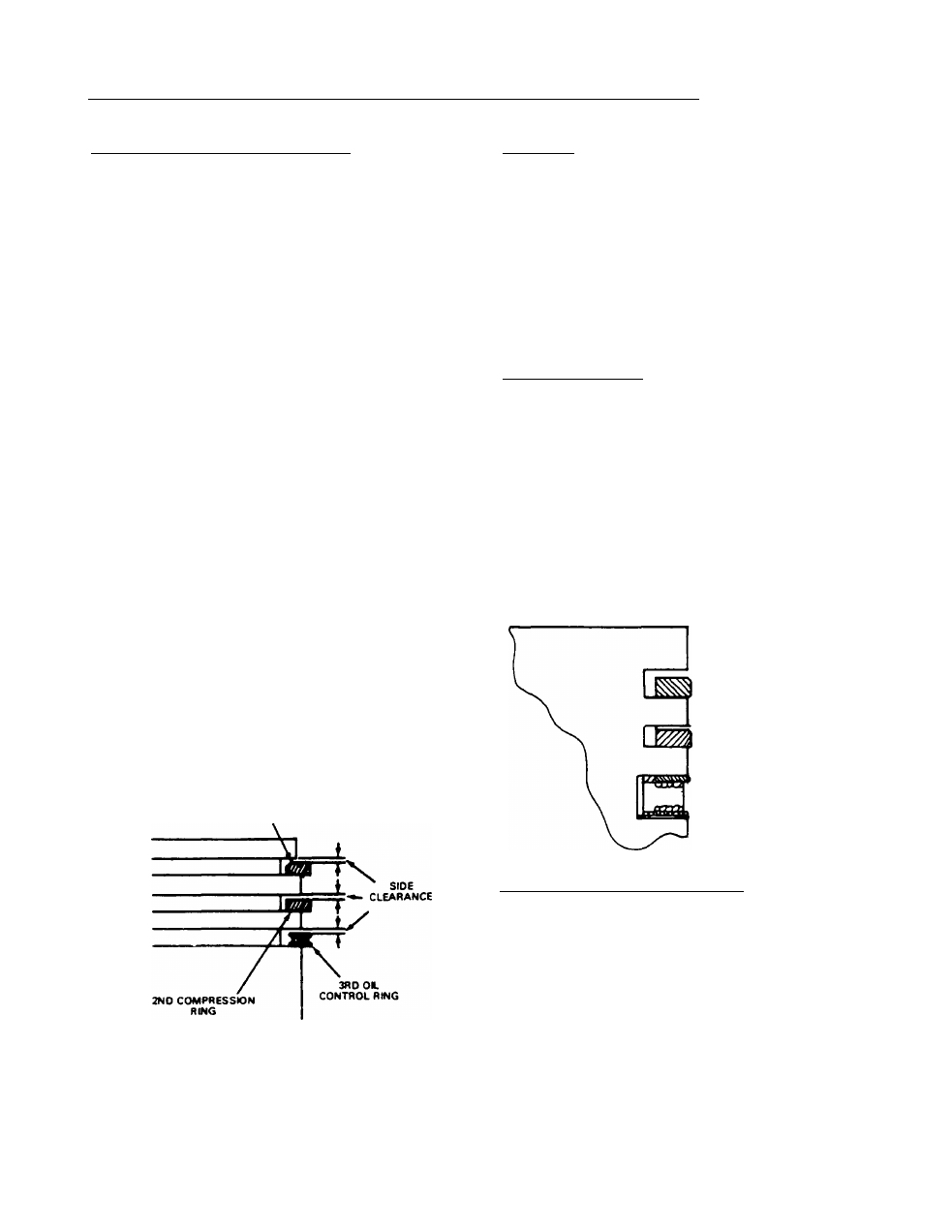
Figure 7. Ring Locations in Piston Grooves
TOP COMPRESSION RING
EITHER SIDE UP
2ND COMPRESSION RING
CHAMFER FACES UP
OIL CONTROL RING
EITHER SIDE UP
CHECKING PISTON RING END GAP:
To check piston rings end gap, proceed as follows
(see Figure 8):
1. Locate a point inside the cylinder that Is 2.75 inches
(70mm) down from top of cylinder. This Is approximately
half-way down.
2. Place the ring into the cylinder. Use the piston to push
the ring squarely into the cylinder to the proper depth.
3. Use a feeler gauge to measure the ring end gap. If end
gap is excessive, rebore the cylinder to take oversize
parts.
TOP RING END GAP (GN190
&
GN220)
DESIGN GAP: 0.005-0.016 inch (0.15-0.40mm)
WEAR LIMIT: 0.024 inch (0.60mm) Maximum
Always replace piston rings in sets.
When removing rings, use a ring expander to pre
vent breakage. Do not spread the rings too far or they
will break.
D
When installing the piston into the cylinder, use a
ring compressor. This will prevent ring brteakage
and/or cylinder damage.
n When installing new rings, deglaze the cylinder wall
with a commercially available deglazing tool.
RING DESCRIPTION:
A piston ring SET consists of (a) a top compression
ring, (b) a second compression ring, and (c) an oil ring
assembly. When installing rings, pay close attention to
the following:
G
The OIL RING is a 3-piece assembly which consists
of two oil rails and an oil spacer ring. Oil rails have
a rounded face and can be Installed with either side
_ up-
□ The second compression ring has an inside chamfer
which must face UP when installing the ring.
G
The top compression ring has a barrel-shaped face
and can be Installed with either side up.
Page 2.3-2