Compression release mechanism, Installing the crankshaft, Installing the camshaft – Generac Power Systems NP-40G User Manual
Page 50
Attention! The text in this document has been recognized automatically. To view the original document, you can use the "Original mode".
Section 2.4- CRANKSHAFT AND CAMSHAFT
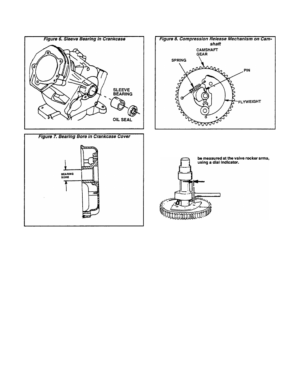
Compression Release Mechanism
A mechanical compression release Is provided on the
camshaft. See Rgure 8. A PIN extends over the cam lobe.
This PIN pushes on the tappet, to lift the valve and relieve
compression for easier cranking. When the engine
starts, centrifugal force moves the FLYWEIGHT outward
against SPRING force. The PIN will then drop back and
allow the engine to run at full compression.
Measure the amount of compression release lift at the
tappet (Rgure 9).
COMPRESSION RELEASE LIFT FOR GN-190 ENGINE
(MEASURED AT TAPPET)
DESIGN LIFT: 0.027-0.055 Inch (0.70-1.40mm)
WEAR LIMIT: 0.023 Inch (0.60mm) Minimum
COMPRESSION RELEASE LIFT FOR GN-220 ENGINE
(MEASURED AT TAPPET)
DESIGN LIFT: 0.020-0.047 Inch (0.50-1.20mm)
WEAR LIMIT: 0.016 Inch (d.406mm) Minimum
Figure 9. Measuring Compression Release Lift
Compression relief lift can also
Installing the Crankshaft
Before Installing the crankshaft, lubricate all bearing
surfaces with engine oil. Use oil seal protectors, to pre
vent damage to seals during installation. Install the
crankshaft as follows:
1. Lubricate all bearing surfaces with engine oil.
2. Install the valve tappets.
3. Support both ends of the crankshaft and carefully
Install Into the crankcase.
4. Rotate the crankshaft until the timing mark (Figure
10) is toward the cam gear side of the crankcase.
Installing the Camshaft
Apply engine oil to the camshaft main bearing and to
bearing bore In crankcase. Carefully install the camshaft
Into the crankcase camshaft bore.
Hold the tappets out of the way during Installation.
Align timing mark on camshaft gear with timing mark on
crankshaft gear (piston will be at top dead center). See
Figure 11.
Page 2.4-3