Valve components removal (continued), Valve service, Valve components removal (con tinued) – Generac Power Systems NP-40G User Manual
Page 39
Attention! The text in this document has been recognized automatically. To view the original document, you can use the "Original mode".
Section 2.2- VALVE TRAIN
Valve Components Removal (Con
tinued)
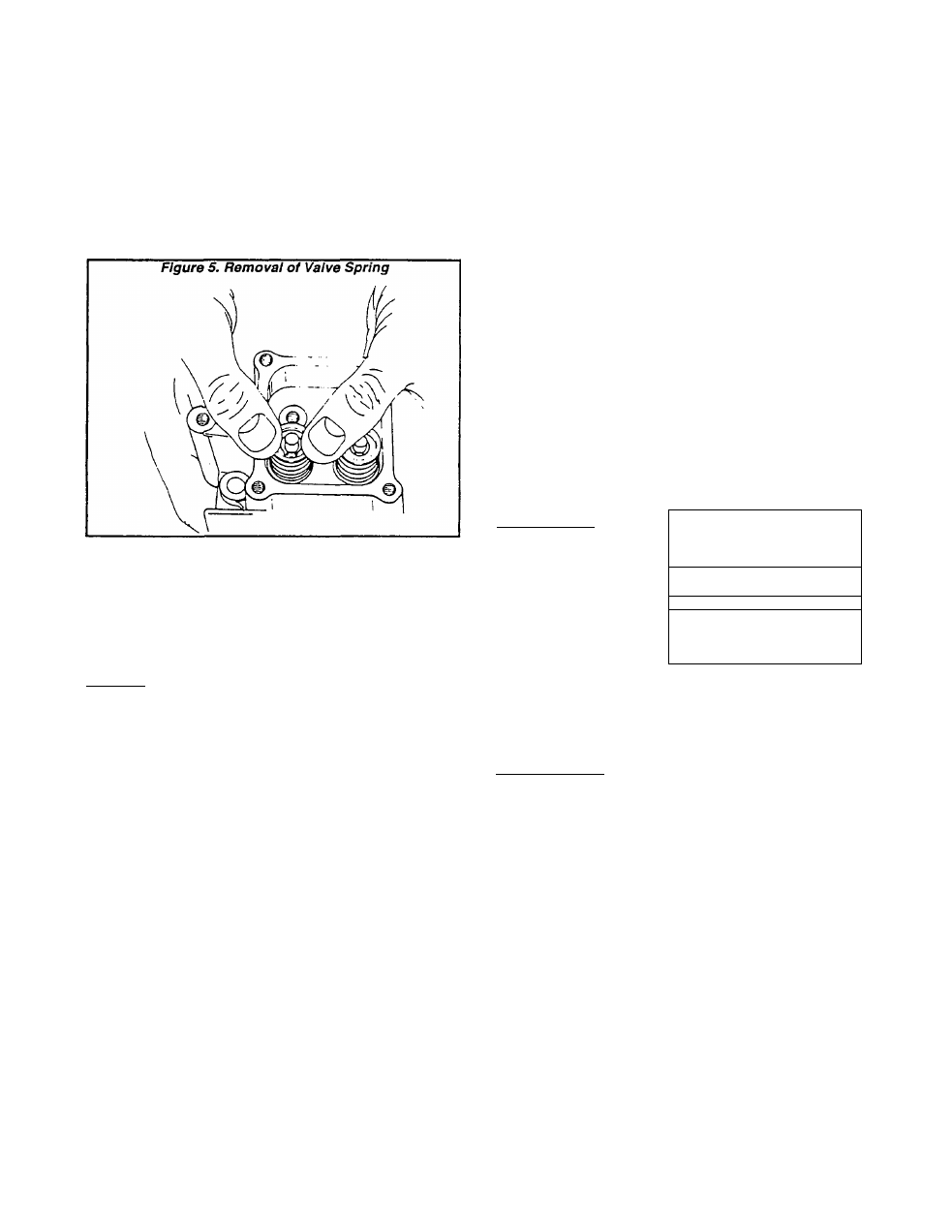
a. While the spring is compressed, slide the larger hole
of the valve spring retainer toward the valve stem.
b. With the larger spring retainer hole around the valve
stem, release the spring.
c. Remove the valve spring retainer, the spring and the
spring washer.
6. Remove the Intake and exhaust valves.
7. Clean all parts. Remove carbon from valve heads and
stems.
8. Inspect the valves and valve seats. Service parts as
outlined under ‘Valve Service*.
Valve Service
VALVES:
Replace valves if they
are damaged, distorted
or if the margin is ground
to less than 0.039 Inch
(1.0mm). If the valves
are In useable condition,
use a valve grinder to
grind the faces to a 45*
angle. Check valve stem
diameter.
After the valves have
been reconditioned, they
should be lapped with a
suitable lapping tool and
valve lapping com
pound.
Figure 6.
0
STEM —
FACE
45"
--------f
MARGIN
NOTE: Proper lapping of valves and valve seats will
remove grinding marks and ensure a good seal
between the valve and Its seat. Be sure to clean
lapping compound from the valve seats and faces.
VALVE MARGIN (GN190)
DESIGN MARGIN: 0.058-0.060 inch (1.48-1.52mm)
WEAR LIMIT: 0.039 inch (0.98mm) Maximum
VALVE MARGIN (GN220)
DESIGN MARGIN: 0.034-0.044 Inch (0.87-1.13mm)
WEAR LIMIT: 0.020 Inch (0.50mm) Maximum
INTAKE VALVE STEM DIAMETER (GN190)
DESIGN DIAMETER: 0.215-0.216 Inch (5.465-5.480mm)
WEAR LIMIT: 0.214 inch (5.435mm) Minimum
INTAKE VALVE STEM DIAMETER (GN220)
DESIGN DIAMETER: 0.274-0.275 inch (6.965-6.980mm)
WEAR LIMIT: 0.273 Inch (6.934mm) Minimum
EXHAUST VALVE STEM DIAMETER (GN190)
DESIGN DIAMETER: 0.214-0.215 inch (5.445-5.460mm)
WEAR LIMIT: 0.213 Inch (5.415mm) Minimum
EXHAUST VALVE STEM DIAMETER (GN220)
DESIGN DIAMETER: 0.273-0.274 Inch (6.945-6.960mm)
WEAR LIMIT: 0.272 Inch (6.909mm) Minimum
NOTE: Design sizes and wear limits of valve train
components can also be found In Part 9 of this
Manual (“SPECIFICATIONS & CHARTS").
VALVE SEATS:
Valve seats are NOT
replaceable. If burned
or pitted, seats can be
reground. Grind seats
at a 45* angle and to a
width of 0.039 Inch
(1.0mm).
Figure 7.
SEAT
^WIDTH
\
,\ V
’1
VALVE SEAT WIDTH (GN190 & GN220)
DESIGN WIDTH: 0.034-0.044 inch (0.87-1.13mm)
WEAR LIMIT: 0.064 inch (1.63mm) Maximum
VALVE GUIDES:
Valve guides are permanently Installed in the cylinder
head and cannot be replaced. If the guides become worn
beyond the wear limit, they can be reamed to accomod
ate a 0.020 Inch (0.50mm) oversize valve stem. Use a
straight shank hand reamer or a low speed drill press to
ream valve guides.
VALVE GUIDES (GN190)
DESIGN DIAMETER: 0.216-0.217 Inch (5.505-5.520mm)
WEAR LIMIT: 0.218 inch (5.54mm) Maximum
VALVE GUIDES (GN220)
DESIGN DIAMETER: 0.237-0.2364 inch (6.02-6.005mm)
WEAR LIMIT: 0.238 inch (6.045mm) Maximum
NOTE: After the valve guides have been oversized,
be sure to recut the valve seats so they will align
with the guides.
Page 2.2-2