Introduction – Generac Power Systems NP-40G User Manual
Page 88
Attention! The text in this document has been recognized automatically. To view the original document, you can use the "Original mode".
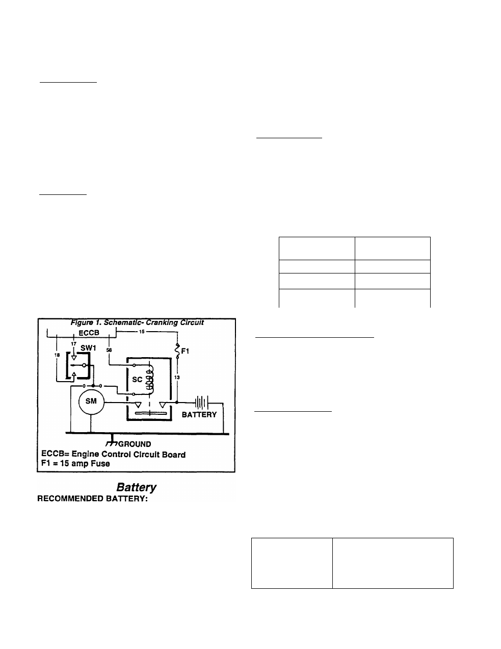
Section 6.3- ENGINE CRANKING SYSTEM
Introduction
COMPONENTS:
The enqine cranking wstem Is shown schemat
ically in Figure 1, below. The system consists of the
following components:
n A 12 volts Battery.
□ A Start-Run-Stop Switch (SW1).
□ A Starter Contactor (SC),
n A Starter Motor (SM).
□ Engine Controller Circuit Board.
□ Interconnecting wires.
OPERATION:
1. Holding the Start-Run-Stop switch (SW1) at
"START* connects Wire 17 from the Engine Con
troller board to frame ground.
a. Engine Controller board action energizes a
crank relay on the board.
b. Closure of the crank relay’s contacts delivers
12 VDC to Wire 56 and to a Starter Contactor (SC).
The Starter Contactor (SC) energizes and its con
tacts close.
2. Closure of the the Starter Contractor (SC) con
tacts delivers battery voltage to the Starter Motor
(SM). The Motor energizes and the engine is
cranked.
The battery is generally supplied by the cus
tomer. Recommended is a battery that meets the
following requirements:
□ Use a 12 VDC automotive type storage battery.
□ For prevailing ambient temperatures above 32*
F. (0* C.), use a battery rated at 70 amp-hours
and capable of delivering 360 cold-cranking
amperes.
□ For prevailing ambient temperatures below 32*
F. (0* C.), use a battery rated 95 amp-hours and
capable of delivering 450 cold-cranking am
peres.
BATTERY CABLES:
Battery cables should be as short as possible
and of adequate diameter. Cables that are too long
or too small in diameter can result In voltage drop.
The voltage drop between battery terminals and the
connection point at generator should not exceed
0.121 volts per 100 amperes of cranking current.
The cables should be carefully selected based on
(a) cable length and (b) prevailing ambient temper
atures. Generally, the longer the cable and the
colder the ambient temperature, the larger the re
quired cable size. The following chart applies:
CABLE LENGTH
Feet (Meters)
CABLE SIZE
0 to 10(0 to 3)
2*
11 to 15(3.4-4.5
0
16 to 20 (4.5 to 6)
000
For warm weather use No. 2 cable up to 20 feet
BATTERY CABLE CONNECTIONS:
1. Connect the cable from the large Starter Contac
tor (SC) lug to the battery post Indicated by a
POSITIVE, POS or (+).
*2:'Connect the cable from Its FRAME GROUND
connection to the battery post indicated by a NEG
ATIVE, NEG or (-).
TESTING A BATTERY:
The best method of testing a battery Is with an
automotive type battery hydrometer. Some “Main
tenance Free" batteries cannot be tested with a
hydrometer.
Most batteries can be tested for both STATE OF
CHARGE and CONDITION as follows:
1. Test for State of Charge:-
a. Follow the hydrometer manufacturer's instruc
tions carefully. Test the specific gravity of the
fluid in all battery cells.
b. If the hydrometer does not have a "Percentage
of Charge" scale, compare the readings obtained
with the following:
SPECIRC GRAVITY
PERCENTAGE OF CHARGE
1.260
100%
1.230
75%
1.200
50%
1.170
25%
Page 6.3-1