Dirt and moisture, Insuiation resistance testers, Stator leads – Generac Power Systems NP-40G User Manual
Page 17: Preparation for tests, Test aii stator windings to ground
Attention! The text in this document has been recognized automatically. To view the original document, you can use the "Original mode".
Section 1.4- INSULATION RESISTANCE
Dirt and Moisture
If moisture Is permitted to remain In contact with the
generator Stator windings, some of It will be retained In
voids and cracks of the winding Insulation. This can
eventually cause a reduction In Insulation resistance and
generator output may be affected.
Winding Insulation In Generac generators Is moisture
resistant. However, prolonged exposure to water, high
humidity, salt air, etc., will gradually reduce the resis
tance of winding Insulation.
Dirt can make the problem even worse, since It tends
to hold moisture Into contact with the windings. Salt, as
from sea air, can also worsen the problem, since salt
tends to absorb moisture from the air. When salt and
moisture combine, they make a good electrical conduc
tor.
Because of the detrimental effects of water, dirt and
salt, the generator should be kept as dry and as clean as
possible. Stator windings should be tested periodically
using a Hi-Pot tester or a Megohmmeter. If insulation
resistance is low, drying of the unit may be necessary. If
resistance is still low after drying, the defective Stator
should be replaced.
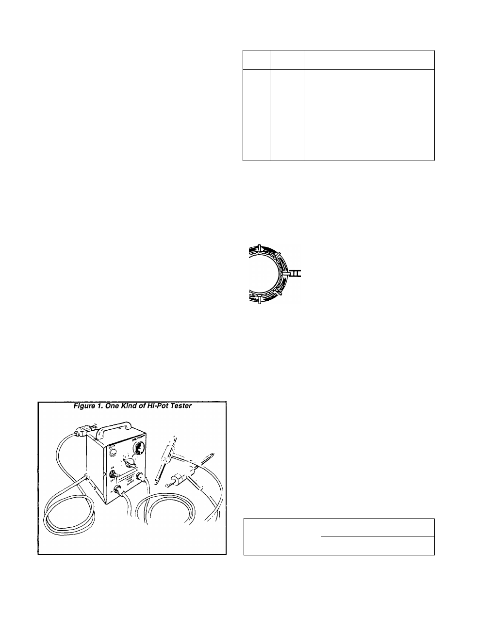
Insuiation Resistance Testers
One kind of Insulation resistance tester Is shown in
Figure 1, below. Other types are commerlally available.
The type shown has a "Breakdown” lamp which turns on
to indicate an Insulation breakdown during the test.
One common type of tester is the "Megohmmeter"
which measures resistance in "Megohms".
CAUTION!
When using a Megohmmeter or any other tester,
be sure to follow the manufacturer’s instructions
carefully. All Stator leads must be isolated from
other components, especially circuit boards, be
fore performina tests. The high voltages used In
testing Insuiation resistance will damage elec
tronic components.
Stator Leads
The following leads are brought out of the Stator and
connected to various components in the unit:
NO.
COLOR
CONNECTS TO
U
77
66
55
SL2
SL1
AC2
AC1
PS1
TIM1
PS2
TIM2
Blue
Brown
Brown
Black
Brown
Orange
Yellow
Gray
Brown
Orange
Yellow
Gray
Main Circuit Breaker CB1
Battery Charge Rectifier BCR
Battery Charge Rectifier BCR
Grounding Terminal
Genistor fG)
Genistor (G)
Genistor (G)
Genistor (G)
CCG Circuit Board (CCB)
CCG Circuit Board i CCB)
CCG Circuit Board l CCB)
CCG Circuit Board (CCB)
Figure 2. Stator Leads
— 55 (BLACK)-*^)
-66 (BROWN)
— 77 (BROWN) — ( O R A N G E )
PS2 (YELLOW)
—TM2 (GRAY) -
-PS1 (BROWN)-
I (BLUE) —«0)
-AC2 (YELLOW)
-AC1 (GRAY)—
-SL1 (ORANGE)^—
----- SL2 (BROWN)-------------
■^0
Preparation for Tests
See Stator leads CHART above. Disconnect and Iso
late all Stator leads. ALL STATOR LEADS MUST BE
DISCONNECTED AND ISOLATED BEFORE STARTING
THE TESTS.
Test Aii Stator Windings to Ground
Connect the ends of all Stator leads together. Make
sure none of the leads are touching any terminal or any
part of the generator.
Connect one Tester probe to the Junction of all Stator
leads; the other Tester probe to a clean frame ground on
the Stator. Apply a voltage of 1000 volts for about 1
second.
Follow the tester manufacturer’s Instructions care
fully. Some "Hl-Pot" testers are equipped with a "Break
down" light which will turn ON to indicate an Insulation
breakdown.
A
ohms"
resistance is on the order of "millions of ohms" or "meg
ohms". The MINIMUM acceptable Insulation resistance
reading for Stators can be calculated using the following
formula.
"Megger" (Megohmmeter) will Indicate the "meg
s’’ of resistance. Normal Stator winding Insulation
MINIMUM INSULATION
GENERATOR RATED VOLTS
RESISTANCE
------------------------------------------- +1
(In “megohniis")
1000
Page 1.4-1