Construction, Components – Generac Power Systems NP-40G User Manual
Page 27
Attention! The text in this document has been recognized automatically. To view the original document, you can use the "Original mode".
Section 1.6- CONTROL PANEL
Construction
The panel Is constructed of sheet metal and Includes
a panel box, a panel back cover and a front control panel.
The panel box Is retained to an enolne-generator divider
plate by five MS screws. Removal of these screws will
permit the panel to be removed from the divider plate and
set out of the way with connecting wires still attached.
This will allow access to components housed In the
control panel.
Components
A heat sink bracket Is attached to the engine-generator
divider plate, for attachment of
a
heat sink to which
a
CCG circuit board and Genistor are mounted. See Items
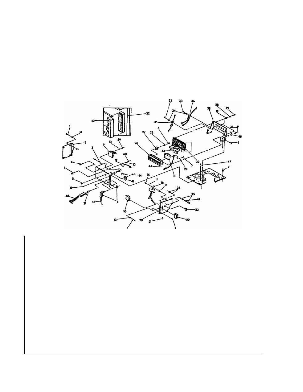
26,31,32 and 38 In the Exploded View of Control Panel.
Other components are also shown In the Exploded View.
Many of tnese components are part of the "ENGINE
ELECTRICAL SYSTEM" (Part 6 of this manual).
Figurer 1. Exploded View of Control Panel
ITEM QTY
DESCRIPTION
ITEM
QTY
DESCRIPTION
1
6
M5 Pan Head Machine Screw
26
1
Heat Sink
2
1
Back Panel Cover
27
1
Battery Charge Rectifier
3
1
Control Panel Box
28
9
M4 Lockwasher
4
2
No. 10-32 Pan Head Screw
29
2
No. 10-32 Hex Nut
5
5
M4 Pan Head Screw
31
1
Genistor
6
8
M5 Screw
32
1
CCG Printed Circuit Board
7
1
Snap Bushing
33
4
M3 Pan Head Screw
8
1
90’ Connector
34
4
M3 Lockwasher
9
1
Engine Controller Circuit Board
35
1
1 ohm Power Resistor
10
1
25 amp circuit breaker
36
1
500 ohm Power Resistor
11
2
M6 Lockwasher
37
4
M6 Screw
12
1
Ignition Module
38
1
Heat Sink Bracket
13
8
M5 Lockwasher
39
4
M4 Pan Head Screw
14
2
M4 Hex Nut
40
2
M5 Hex Nut
15
2
M6 Hex Nut
41
1
Terminal Block
16
1
Ignition Coll Assembly
42
1
12-pln Connector
17
2
Ignition Coll Spacer
43
1
Genistor Harness
18
4
No. 8 Flatwasher
44
1
Ground Wire
20
1
Front Control Panel
45
1
Customer Wiring Harness
21
2
Snap Bushing
46
1
Remote Panel Harness
22
1
Start-Stop Switch
47
1
Snap Bushing
23
1
Fuel Primer Switch
48
2
Wiring Harness Clamp
24
1
15 amp Fuse
49
1
Panel Harness (Not Shown)
25
1
Fuse Holder
Page 1.6-1