Oil pump (continued), Crankshaft oil seals, Pressure relief valve – Generac Power Systems NP-40G User Manual
Page 78: Breather assembly
Attention! The text in this document has been recognized automatically. To view the original document, you can use the "Original mode".
Section 5.1- ENGINE OIL SYSTEM
Oil Pump (Continued)
INSPECTION (CONT’D):
Inspect the outer drive pins on the camshaft
Look for breakage, bending, other damage. These
are roll pins which can be removed and replaced.
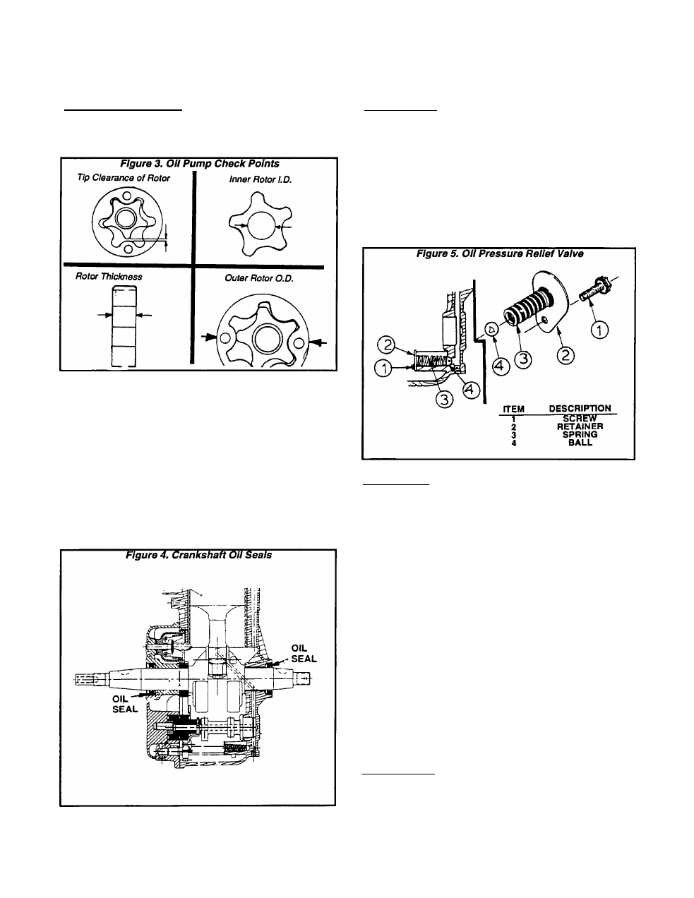
Crankshaft Oil Seals
An oil seal Is provided In the crankcase and in
the oil sump, to prevent leakage past the crankshaft
journals. See Figure 4.
A defective or leaking seal can be replaced. If the
crankshaft has been removed from the engine, old
seals can be removed by tapping out with a screw
driver or punchinq them out from inside. Oil seal
pullers are available commercially, for seal removal
with the crankshaft installed.
Always use a seal protector when Installing the
crankshaft into its crankcase bore and when In
stalling the oil sump over the crankshaft.
Pressure Relief Valve
DESCRIPTION:
A ball type pressure relief valve Is located In a
bore of the crankcase. The ball and spring are
retained in the crankcase bore by a spring retainer.
The Relief Valve serves to limit oil pressure to a
maximum value. The ball will remain against Its
seat as long as oil pressure In the crankcase oil
passage is below approximately 30 psi (29 kg/cm^).
Should oil pressure increase above that value, the
ball will be forced off Its seat to relieve excess
pressure Into the crankcase.
INSPECTION:
Remove the 8mm screw that retains the spring
RETAINER to the crankcase interior. Remove the
RETAINER, SPRING and BALL. Clean all parts In
solvent.
Inspect the BALL and RETAINER for damage,
excessive wear. Replace any damaged or worn
components. Inspect the SPRING and replace If
damaged or worn.
Apply a known test load to the SPRING, sufficient
to compress the spring to a length of 1.03 inch
(26.3mm). The amount of the test load at the stated
spring length should be as follows:
FORCE REQUIRED TO COMPRESS
RELIEF VALVE SPRING TO 1.03 INCH (26.3mm)
0.86-0.95 pounds (0.43-0.39 kg)
If the test load at the stated length is not within
limits, replace the SPRING.
Breather Assembly
DESCRIPTION:
A crankcase breather Is located In the crankcase
assembly.
Page 5.1-2