Testing the battery charge circuit (continued), Testing the ccg circuit board – Generac Power Systems NP-40G User Manual
Page 24
Attention! The text in this document has been recognized automatically. To view the original document, you can use the "Original mode".
Section 1.5- COMPONENTS TESTING
Testing the Battery Charge Circuit
(Continued)
SYMPTOMS OF CIRCUIT FAILURE:
It is difficult to determine if the battery charm
circuit is operating without testing for correct volt
age. If you suspect the battwery charge circuit Is
defective,
the
following
symptoms
will
usually
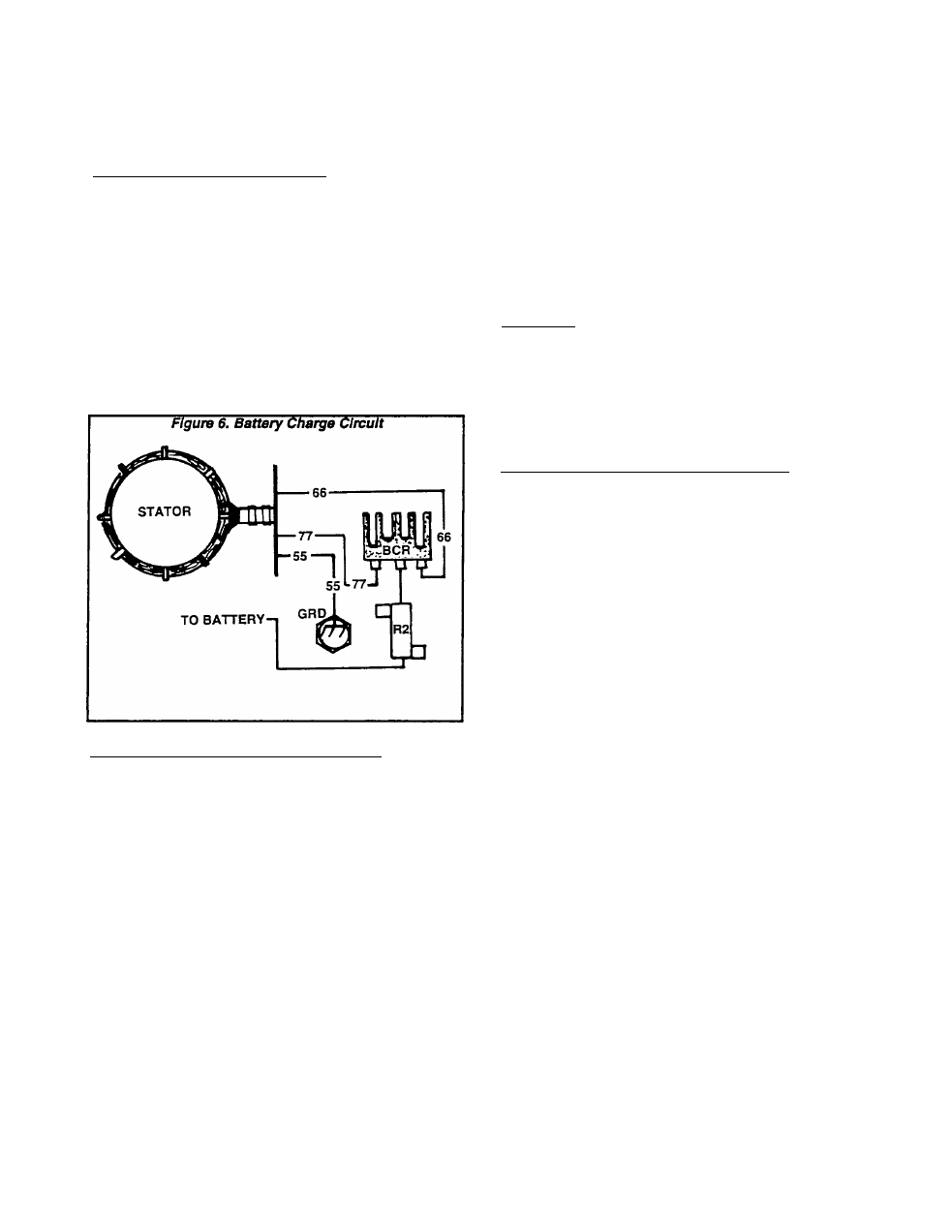
point to a cause of the problem. See Figure 6.
1. If no AC voltage can be measured across Stator
connections at the Battery Charge Rectifier (BCR),
an open circuit condition probably exists in Wire 66
(Brown), or Wire 77 (Brown).
2. If AC voltage is available to the Wire 66 and 77
terminals at the battery Charge Rectifier, but no
voltage or a low voltage Is measured between the
BCR’s Wire 55 terminal and ground, the Battery
Charge Rectifier (BCR) Is defective.
TESTING THE BATTERY CHARGE CIRCUIT:
Test the Battery Charge winding as follows:
1. Disconnect Wire 77 at the Battery Charge Recti
fier (BCR).
2. Disconnect Stator output Wire 66 at the Battery
Charge Rectifier (BCR).
3. Disconnect Wire 55.
4. Set a VOM to its ”Rx1" scale and zero the meter.
5. Connect the VOM test leads across Wires 77 and
55, then across Wires 66 and 55. Note the resis
tance reading in both cases. Replace Stator As
sembly, If defective.
BATTERY CHARGE WINDING RESISTANCE
ACROSS WIRES 66 TO 55 s 0.037-0.042 Ohm
ACROSS WIRES
77
TO
55
s 0.037-0.042 Ohm
6. Use a VOM to measure AC voltage at the Wires
66 and 77 terminals of the Battery Charge
Rectifier, with the unit running. If no AC voltage is
measured, an open circuit exists in the wire 66 or
77 circuit.
7. With engine running, use a VOM to check for DC
voltage between the Battery Charge Rectifiers
Wire 55 and frame ground. If AC voltage was pre
sent in step 6, but DC voltage is NOT present in
this stem, the Battery Charge Rectifier (BCR) is
d6f6CtiVG.
Testing the CCG Circuit Board
GENERAL:
It is difficult if not impossible to test the CCG
circuit board in the field. Generally, if the other
components in the AC generator system have
tested good, you may assume that any problem is
In the CCG circuit board.
NOTE: Also refer to “CCG Circuit Board" on Pages
Ï.2-4,
1^-5, and 1^-6.
SYMPTOMS OF CIRCUIT BOARD FAILURE:
1. If the engine starts, but the Stepper Motor does
not move, and engine shuts down after several
seconds, the CCG circuit board’s micro-controiler
may not be operating.
2.
A failure of the circuit board’s Stepper Motor
drive can result in the following:
a.
Engine starts, but Stepper Motor does not
move.
The
engine
accelerates
uncontrollably
and shuts down when engine speed exceeds
4500 rpm.
b.
Engine starts, but Stepper Motor does not
move. The following symptoms occur:
(1) Engine appears to operate too slowly.
(2) Engine is not able to handle the load and unit
operates at low AC output voltage.
(3) After several seconds under load, AC output
voltage is turned off (overload condition).
3. If the engine can be started, but shuts down after
several seconds, a timing detection faiiure may
have occured (Timing winding. Wires TIM1, T1M2).
4. if the engine speed and output voltage are erratic
under constant load, but the AC output does not
turn off intermittently, erratic timing detection may
have occured (Timing winding. Wires TIM1, TIM2).
NOTE:
Timing
detection
Involves
the
circuit
board’s ability to detect "zero crosslrws" of the
sine wave (see “Alternating Current", Pages 1.1-1
and 1.1-2). The CCG clrculfboard must detect both
zero VOLTAGE and zero CURRENT crossings If the
system Is to operate properly. This “zero crossing“
detector Is used to synchronize an Internal clock
on the circuit board. The frequency of the Input
waveform la measured by the circuit board and
checked against a "reference“ frequency. The
board then calculates a frequency divisor. By
counting “zero voltage crossings“, an Internal ret-
erence output polarity Is generated. The Genistor
switch with the maximum potential In the direction
of the Internal reference Is gated.
Page 1.5-4