General, How it works – Generac Power Systems NP-40G User Manual
Page 84
Attention! The text in this document has been recognized automatically. To view the original document, you can use the "Original mode".
Section 6.1- ENGINE DC CONTROL SYSTEM
General
The engine DC control system consists of all
those electrical components required for cranking,
starting and running the engine. These compo
nents include the following:
1. Engine cranking system components
a. A 12 VDC battery.
b. A Start-Run-Stop Switch (SW1).
c. A Starter Contactor (Starter Relay)- (SC).
d. A Starter Motor (SM).
2. An Engine Controller Circuit Board (ECB).
3. A Fuel Primer Switch (SW2).
4. Engine Ignition System Components.
a. Ignition Module (IM).
b. Ignition Stator (IS).
c. Ignition Coil (1C).
d. Spark Plug (SP).
5. Engine Protective Devices
a. Low Oil Pressure Switch (LOP).
b. High Oil Temperature Switch (НТО).
6. An optional Remote Panel.
Figure 1.
How it Works
ENGINE NOT RUNNING:
1. Battery output (12VDC) Is
available to the contacts of
a starter contactor (SC).
However, the contacts are
open.
2. Battery output is deliv
ered to Terminal J3 of an
Engine Controller circuit
board, via Wire 13, a 15 amp
fuse, and Wire 15. Circuit
board action holds this cir
cuit open.
3. Battery output is avail
able to a Battery Charge
Rectifier (BCR) via Wire 13,
15 amp Fuse (FI), Wire 15,
a Resistor (R2) and Wire
15A.
PRIMING:
NOTE: On units with LP gas fuel system, the Fuel
Lockoff Solenoid (FS) will be turned on by closing
the Primer Switch.
CRANKING:
When the Start-Run-Stop Switch is held at
"START“, the Wire 17 circuit from the Engine Con
troller circuit board Is connected to frame ground.
Circuit board action then Initiates the following
events:
1. Battery voltage Is delivered to the Starter Con
tactor (SC) coil via Wire 56.
a. The SC coil energizes and its contacts (SC)
close.
b. Closure of SC contacts deliver battery voltage
to the Starter Motor (SM) via Wire 16. The engine
cranks.
2. Battery voltage Is delivered to the Wire 14 circuit.
a. The Fuel Pump (FP) turns on.
b. Power is available to the Ignition Module (IM)
and ignition occurs.
When the Primer Switch
(SW2) is closed, battery
voltage is delivered to the
engine Fuel Pump via Wire
13, 15 amp Fuse (FI), the
Switch contacts (SW^ and
Wire 14A. The Fuel Pump
will operate to draw fuel
from the tank and "prime"
the fuel lines.
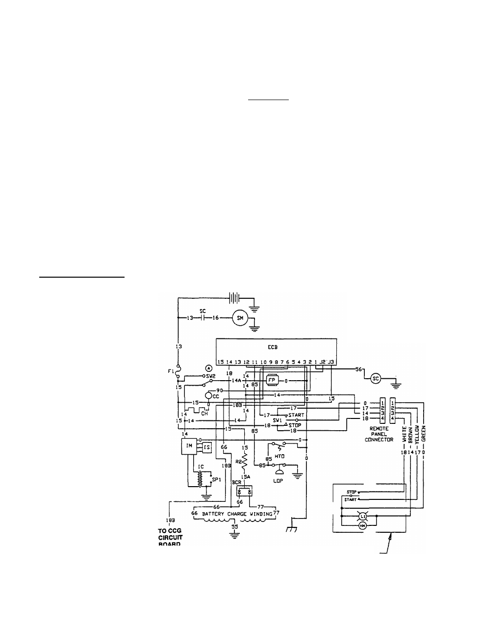
Schematic- Engine DC Control System
CUSTOMER SUPPLIED
BATTERY
BCR . BAT^^HARQC RECTIRER
PP -
FUEL PUMP
(QASOUNS)
HM • HQURMSTER(OPnON&)
НТО • НЮН OIL TEMP. SWITCH
1
C - кантон
coil
IM • кантон MODULE
18 ■ IQHmOH STATOR
LI - RUN LAMP fOPTIOHAL)
LOP - OIL PRESSURE SWITCH
R2 « l O H f c L W WATT RESISTOR
SC • STARTER COHTACTOR
SM ■ STARTER MOTOR
8W1 « 8TART*STOP SWITCH
f
W2 - PRIMER SWITCH
PI • SPARK PLUG
R E M O T E
P A N E L
( O P T I O N A L )
Page 6.1-1