Connecting rod, Assembly and installation, Cylinder service – Generac Power Systems NP-40G User Manual
Page 46
Attention! The text in this document has been recognized automatically. To view the original document, you can use the "Original mode".
Section 2.3- PISTON, RINGS, CONNECTING ROD
SECOND RING END GAP )GN190 & GN220)
DESIGN GAP: 0.006-0.016 Inch (0.15-0.40mm)
WEAR LIMIT: 0.024 Inch (0.60mm) Maximum
OIL RING END GAP (GN190 & GN220)
DESIGN GAP: 0.015-0.055 Inch (0.38-1.40mm)
WEAR LIMIT: 0.062 Inch (1.60mm) Maximum
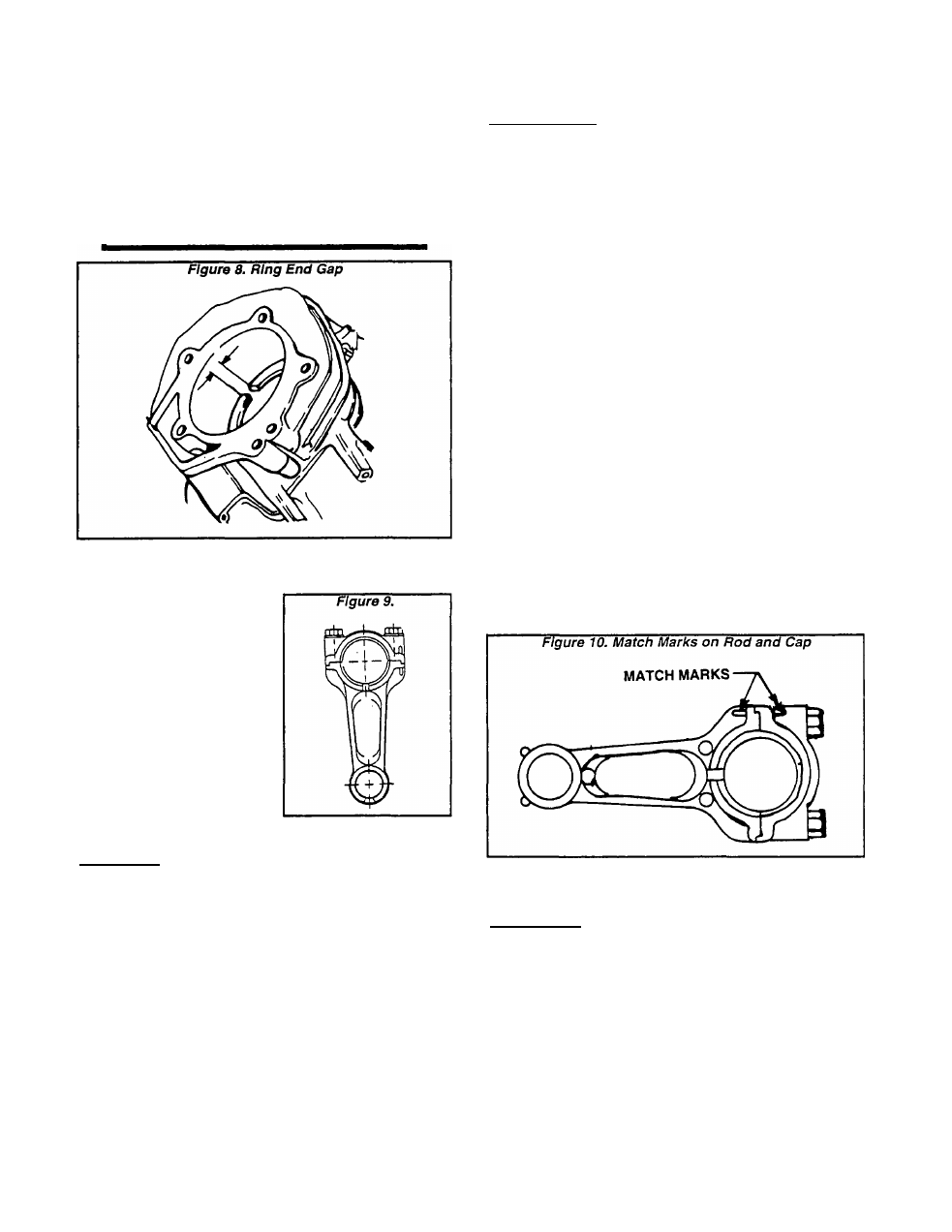
Connecting Rod
Tha connecting rod Is man
ufactured of die cast alumi
num. Alignment marks are
provided on the rod and on the
connecting rod cap. Be sure to
align these marks when as
sembling the rod to the crank
shaft. Connecting rod bolts
are of the "washerless" type.
The connecting rod and the
connecting rod cap are a
matched set and must be re
placed as a matched set
Assembly and Installation
ASSEMBLY:
Use a ring expander when Installing rings Into the
piston ring grooves. Install the OIL RING ASSEMBLY
first. Then, Install the second compression ring with its
Inside chamfer facing up. Finally, install the top com
pression ring.
When assembling the piston, connecting rod and wrist
pin, the assembly marks on the piston must be toward
the flywheel side of the engine.
Coat the wrist pin, wrist pin bore In piston, and wrist
pin bore in the rod with engine oil. Install one snap ring
Into the piston’s wrist pin bore. Then, assemble the
piston to the rod. Slide the wrist pin through one piston
bore, through the rod bore, and through the second
piston bore until It contacts the snap ring. Then, Install
the second snap ring into the piston bore.
INSTALLATION:
Coat the cylinder walls with engine oil, as well as the
crank throw, connecting rod bearing and connecting rod
cap bearing. Then, Install the rod and piston assembly
as follows:
1. Use a ring compressor to compress the rings Into the
piston ring grooves. MAKE SURE ALL RINGS ARE
FULLY COMPRESSED INTO THEIR GROOVES.
2. Guide the connecting rod Into the cylinder, with as
sembly mark on piston toward the flywheel side of en
gine.
3. When the ring compressor contacts top of cylinder,
use a wood hammer handle to gently tap the piston down
into the cylinder.
4. Check that the connecting rod’s large diameter bear
ing is coated with oil, as well as the crank throw and the
connecting rod cap.
5. Guide the large end of the connecting rod onto the
crankshaft Install the connecting rod cap. The match
mark on the cap must be aligned with an Identical mark
on the rod (Figure 10).
6. Install the corinecting rod cap bolts and tighten to the
proper torque.
TIGHTENING TORQUE
CONNECTING ROD CAP BOLTS (GN190 & GN220)
10 foot-pounds (1.36 N-m)
NOTE: The connecting rod can be Installed In either
direction. That Is, the cap marks on the rod and cap
may face toward the Installer or away from the
Installer. The only requirement Is that the assembly
mark on top of piston be toward the flywheel side
of engine.
Cylinder Service
INSPECTION:
Check the cylinder for dirty, broken or cracked fins.
Also look for worn or scored bearings, or a scored
cylinder wall. Check the cylinder head mounting surface
for warpage. If the head is warped, it must be replaced.
If the cylinder bore Is worn (as evidenced by excessive
ring end gap), the cylinder should be replaced or rebored
to 0.010 or 0.020 (0.25 or 0.50mm) oversize.
After reboring the cylinder to a specific oversize, In
stall an Identically oversize piston along with identically
oversized rings.
Page 2.3-3