Engine speed, Throttle linkage adjustment – Generac Power Systems NP-40G User Manual
Page 61
Attention! The text in this document has been recognized automatically. To view the original document, you can use the "Original mode".
Section 3.4- CARBURETOR
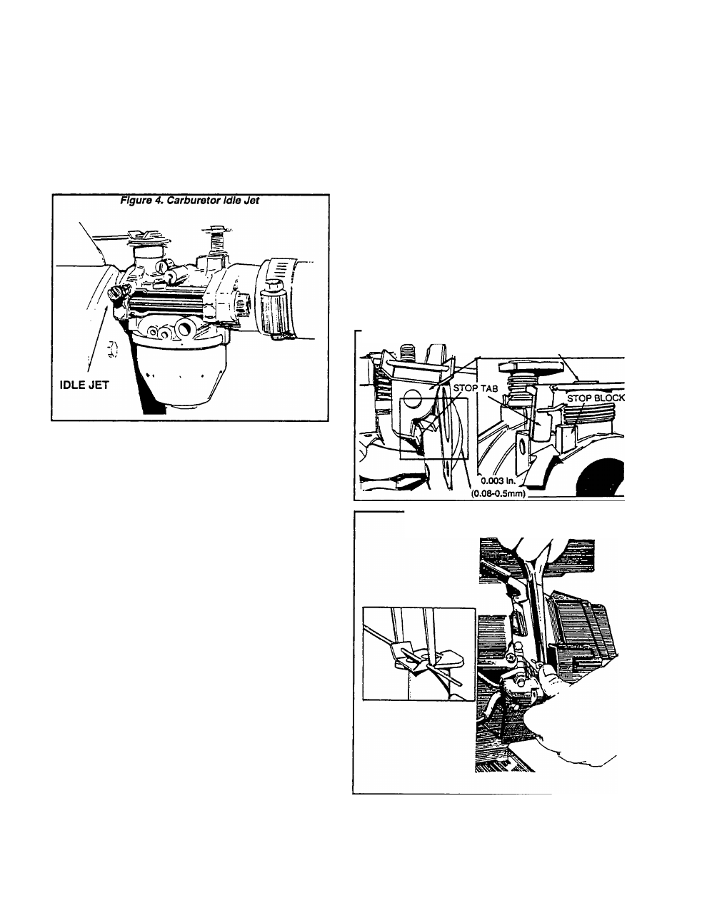
1. with enqine running at no-load, turn the IDLE JET
clockwise (leaner) until engine speed starts to decrease
or fluctuate.
2. Turn the IDLE JET counterclockwise (richer) until
engine speed starts to decrease or fluctuate or until
black smoke comes from exhaust.
3. Very SLOWLY turn the IDLE JET clockwise (leaner)
until engine speed just stabilizes or until black smoke
just stops coming from exhaust 00 NOT turn the JET
excessively lean.
Engine Speed
Engine speed is controlled by the CCG circuit
board. That circuit board signals a stepper motor
which moves the throttle linkage. Engine speed will
vary in response to changes In generator AC output
voltage.
The circuit board monitors the demand for power
and adjusts the engine speed accordingly. This
permits the engine to deliver only the power
needed.
NOTE: Do NOT attempt to accelerate the enalne
manually by grasping the throttle or throttle link
age. This win cause the system to enter a fault
condition and terminate generator AC output.
Throttle Linkage Adjustment
If necessary, the length of the linkage between
the stepper motor and the carburetor throttle lever
arm can be adjusted. This adjustment helps to
establish the proper travel relationship of the link
age. If the adjustment is not correct, the CCG board
will not be able to control the full range of engine
speed. The following conditions might occur:
G
If the throttle linkage Is set too short, the system will
not be able to provide wide open throttle or full
power conditions.
G
If the linkage Is set too long, the system will not be
able to provide closed throttle or no power condi
tions.
Use the following procedure to ensure the link
age rod is properly adjusted:
1. Start the engine and immediately shut it down. As the
engine coasts to a stop, observe from above the engine
as the carburetor throttle lever rotates counterclockwise.
2. There should be a gap of about 0.003 inch (0.08-0.5mm)
between the stop tab on the throttle lever arm and the
stop block on the carburetor casting. See Figure 5.
CAUTION!
The next step Involves bending a spring clip. Do
NOT overbend the clip or it may lose its clamping
force.
3. Use pliers to lightly compress the spring clip on the
carburetor lever arm (Figure 6). This permits the linkage
rod to slide freely through the clip. With the clip com
pressed, rotate the throttle lever in the appropriate direc
tion until there is a 0.003 Inch (0.08-0.5mm) gap.
4. Release the spring clip to lock In the adjustment
Figure 5. Set Between Stop Tab and Stop Block
THROTTLE LEVER ARM
Figure 6. Adjusting Throttle Linkage
Page 3.4-3