Fuel filter – Generac Power Systems NP-40G User Manual
Page 57
Attention! The text in this document has been recognized automatically. To view the original document, you can use the "Original mode".
Section 3.3- FILTER & FUEL PUMP
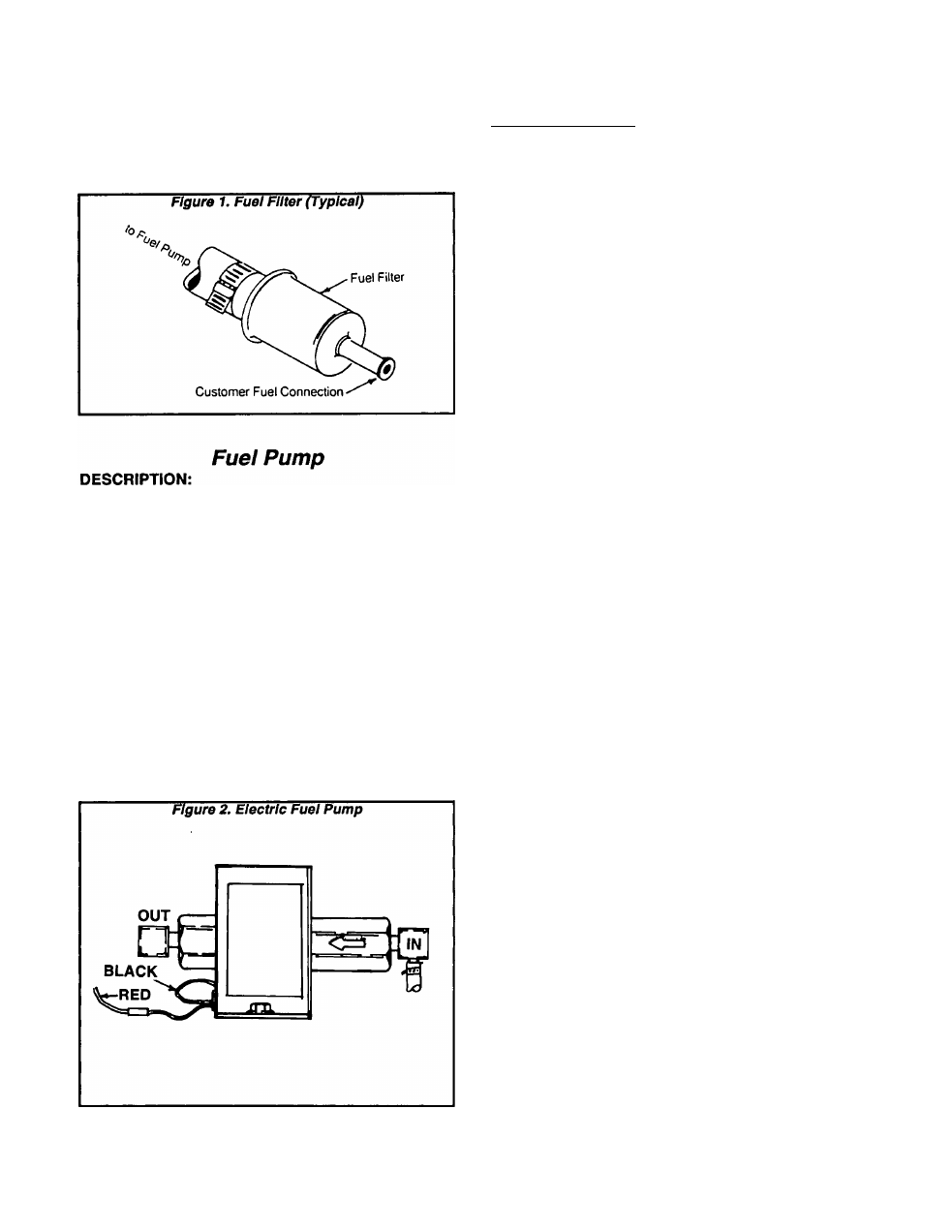
Fuel Filter
The fuel filter should be removed end replaced every
100 hours of operation or once each year, whichever
occurs first
The 12 voKs DC electric fuel pump has a zinc plate
finish. Flow through the pump Is positively shut off
when it is not operating. The pump Is actually rated at a
voltage of 8 to 16 VDC, but has a nominal voltage rating
of 12 VDC.
Current draw of the pump at nominal voltage Is ap
proximately 1.4 amperes maximum.
Pressure rating of the pump at zero delivery is 2.0 to
3.5 psi.
Two wires are brought out from the pump. The black
wire Is grounded by connecting It to a pump mounting
bolt The red wire is Identified as Wire No. 14A. The pump
will operate whenever:
□ The FUEL PRIME switch on the generator panel is
actuated to Its "ON” position.
□ During engine startup and running conditions when
the Engine Controller circuit board energizes the
Wire No. 14 circuit
TESTING THE PUMP:
1. The pump coll can be tested for an open or shorted
condition as follows:
a. Test for "Open":
(1)
Disconnect the RED pump wire at Its "bullet* lug.
(2) Set a VOM to Its *Rx1" scale and zero the meter.
(3) Connect one meter test probe to the RED pump
wire, the other test probe to terminal end of the
pump’s BLACK lead. The VOM should Indicate
pump coll resistance.
FUEL PUMP NOMINAL COIL RESISTANCE
ABOUT 0.75 to 1.00 ohm
b. Test for "Shorted" condition:
(1) Disconnect the RED and the BLACK fuel pump
leads.
(2) Set a VOM to its "Rxl0,000" or "RxlK" scale and
zero the meter.
(3) Connect one VOM test lead to the pump RED
lead, the other test probe to the pump body. The
meter should read "Infinity".
2. Pump operation can be tested as follows:
a. Disconnect the fuel line from the outlet side of the
fuel pump.
b. Make sure a supply of fuel Is available to the inlet
side of the pump.
c. The RED lead from the pump must be connected
properly Into the circuit The pump’s BLACK lead must
be connected at the pump mounting bolt
d. Actuate the Fuel Prime switch on the generator
panel. The pump should operate and should pump fuel
from the outlet side.
NOTE: If desired, a pressure aauge can be attached
to the pump’s outlet side. Pump outlet pressure
should be 2.0 to 3.5psI.
Page 3.3-1