Testing the stepper motor – Generac Power Systems NP-40G User Manual
Page 66
Attention! The text in this document has been recognized automatically. To view the original document, you can use the "Original mode".
Section 3.6- SPEED CONTROL SYSTEM
Figure 1, Speed Control System
CCG BOARD
CONNECTOR
RED
ORANGE
YELLOW
BROWN
BLACK
STEPPER
MOTOR
GENERAL:
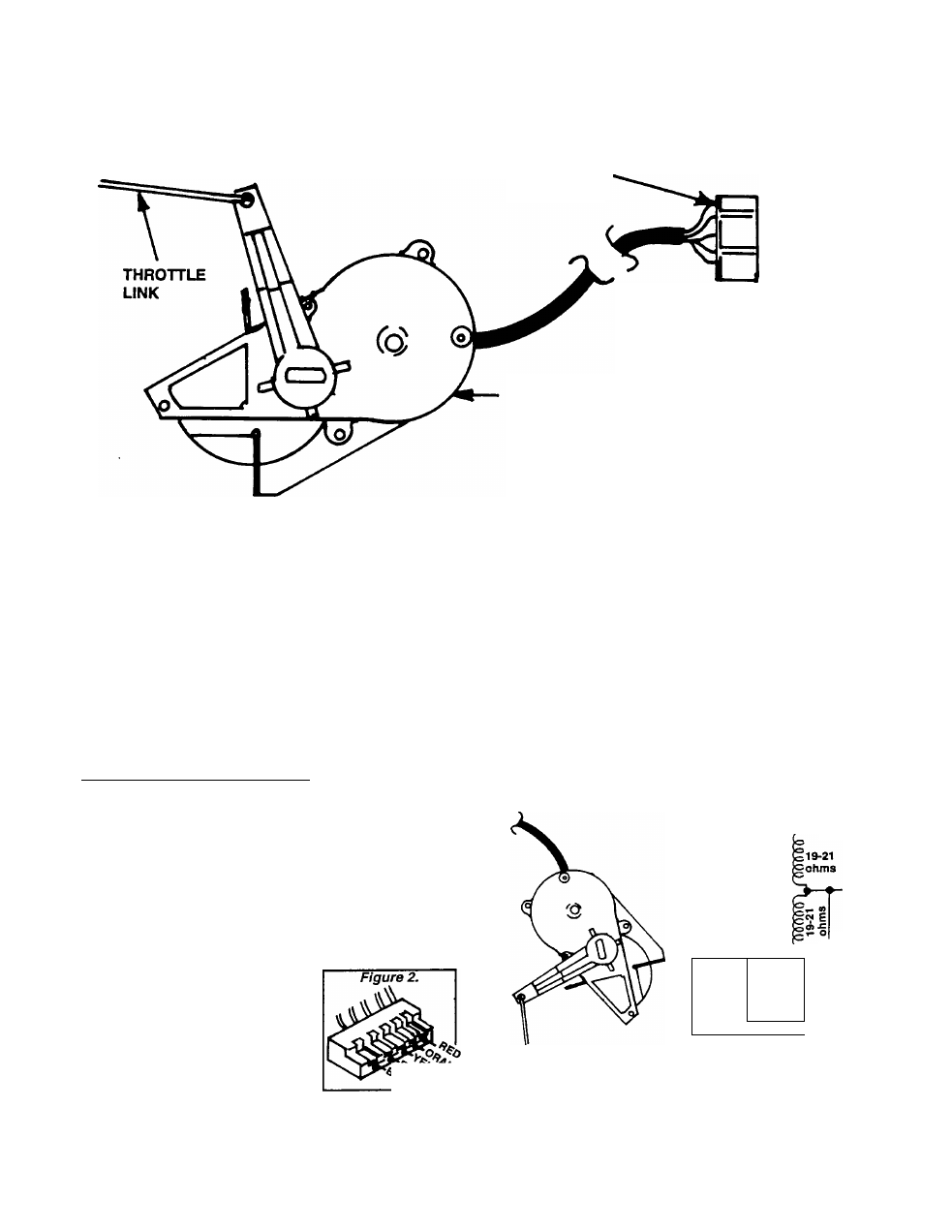
Testing the Stepper Motor
TESTING FOR SHORTED CONDITION:
The Stepper Motor consists of an electric motor
plus a small gearbox. It is shown pictoriaily and
schematically in Figure 3. The four (4) motor wind
ings can be tested for (a) continuity and (b) shorts
to the case.
it is difficult to perform an operational test of the
motor since the amount of motor arm movement is
so small.
TESTING FOR OPEN CONDITION:
To test the motor windings for an open circuit
condition, proceed as follows:
1. Unplug the Stepper Motor connector from its recepta
cle on the CCG circuit board.
2. Set a volt-ohm-milllammeter (VOM) to its "Rx1“ scale
and zero the meter.
3. Connect one VOM test probe to the connector pin to
which the RED wire attaches. This is the -t-DC side of all
windings. Then, connect the other VOM test probe as
follows:
a. To the ORANGE wire connector pin. Approxi
mately 19-21 ohms should be
indicated.
b. To the YELLOW wire con
nector pin. About 19-21 ohms
should be read.
c. To the BROWN wire pin for
a reading of 19-21 ohms.
d. To the BLACK wire connec
tor pin for a reading of about
19-21 ohms.
1. Set the VOM to its "Rxl 0,000“ or “Rxl K“ scale and zero
the meter.
2. Connect one VOM test probe to the RED wire connecv-
tor pin, the other test probe to the Stepper Motor case.
The meter should read "infinity“. Any reading other than
"infinity“ Indicates a shorted winding.
Replace the Stepper Motor if It fails any part of the test.
Figure 3. The Stepper Motor
ORANGE
RED
^YELLOW
imm,
19-21
ohms
JOOOOir
19-21
ohms
■BROWN
I I
-BLACK
Pictorial
Schematic
Page 3.6-2