Introduction to oil system, Oil flow, Oil pickup screen – Generac Power Systems NP-40G User Manual
Page 77: Oil pump
Attention! The text in this document has been recognized automatically. To view the original document, you can use the "Original mode".
Section 5.1- ENGINE OIL SYSTEM
Introduction to Oil System
The engine oil system serves to (a) reduce fric
tion between parts, (b) cool the engine, and (c)
establish a slightly negative pressure In the crank
case to prevent oil leakage. Major components that
will be discussed in this section Include the follow
ing:
□ Oil PIckupScreen.
□ Oil Pump.
□ Crankshaft OH Seals.
□ Pressure Relief Valve.
□ Breather Assembly.
□ Oil Sump.
n Oil Filter Support Assembly.
Oil Flow
See Figure 1. The oil pump draws oil from the oil
sump through an oil pickup screen and delivers It
to the areas requiring lubrication as follows:
1. Through a cored channel In the oil sump to the crank
case Journal at one end of the crankshaft
2. Through the hollow camshaft to the camshaft bearing.
3. Through a cored passage In the crankcase to the
crankshaft Journal.
4. Through the crankshaft to the crankpin and connect
ing rod bearing.
Oil Pickup Screen
DESCRIPTION:
The oil pickup screen consists of a cylindrical
screen which Is open at one end only. The screen’s
open end fits over a tubular protrusion In the oil
sump. Just behind the oil filter support. Also see
"
Oil Filter Support Assembly".
INSPECTION:
To gain access to the screen, remove the oil filter
support and its gasket. Pull the screen off Its
tubular protrusion. Clean the screen In solvent,
then Inspect for damage. Replace the screen If
necessary.
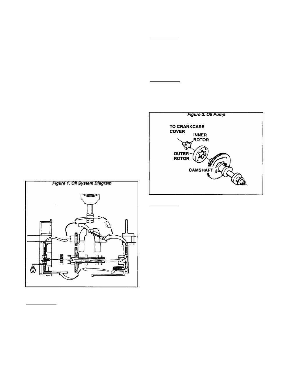
Oil Pump
DESCRIPTION:
The oil pump Is of the trochoid type. Its Inner
rotor rotates on a shaft provided In the camshaft
bore of the oil sump. The outer rotor Is Installed
over two drive pins on the end of the camshaft and
Is driven by camshaft rotation.
INSPECTION:
See Figure 3. Inspect the Inner and outer rotors
of the pump for damage and wear. Use a feeler
gauge to check tip clearance of the rotor (measured
on the shaft in the oil sump). Check the bore Inner
diameter and the thickness of the Inner rotor. If
wear limits are exceeded, replace the appropriate
part(s).
PUMP TIP CLEARANCE
(MEASURED ON SHAFT IN OIL SUMP)
DESIGN CLEARANCE: 0.0000-0.0010 Inch
(0.000-0.025mm)
WEAR LIMIT: 0.004 Inch (0.105mm) Maximum
INNER PUMP ROTOR BORE
DESIGN BORE: 0.354-0.355 Inch (9.000-9.019mm)
WEAR LIMIT: 0.357 Inch (9.034mm) Maximum
INNER ROTOR THICKNESS
DESIGN THICKNESS: 0.312-0.315 Inch (7.95-8.00mm)
WEAR LIMIT: 0.311 Inch (7.90mm) Minimum
Replace any part that is damaged or worn exces
sively. The shaft on which the inner rotor rotates
is NOT repiaceabie (oil sump must be replaced).
Page 5.1-1