Valve service (continued), Valve components installation – Generac Power Systems NP-40G User Manual
Page 40
Attention! The text in this document has been recognized automatically. To view the original document, you can use the "Original mode".
Section 2.2- VALVE TRAIN
Valve Service (Continued)
VALVE TAPPETS!
Valve tappets can be
removed during re
moval of the engine
camshaft. Intake and
exhaust valve tappets
are Identical. However,
once a wear pattern
has been established
the two tappets should
not be Interchanged.
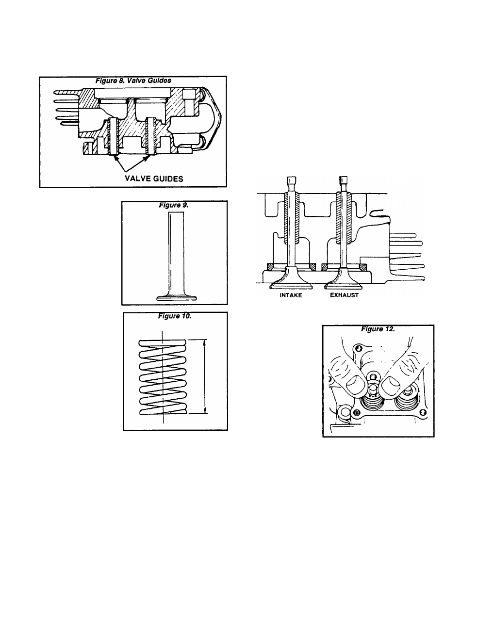
VALVE SPRINGS:
Inspect the valve
springs. Measure the
spring free length.
Also, cneck the amount
of force required to
compress the spring to
a length of 1.39 Inch
(35.2 mm). Replace any
damaged or defective
spring.
VALVE SPRING FREE LENGTH
GN190:1.910 Inch (48.48mm)
GN220: 2.074 Inch (52.69mm)
FORCE REQUIRED TO COMPRESS SPRING
TO 1.39 INCH (35.2MM)
GN190:14.8-16.2 lbs (6.7-7.4kg)
GN220:19.8-21.8 lbs (9.0-9.9kg)
Valve Components Installation
After the valve train parts have been Inspected and (If
necessary) serviced. Install them as follows:
1. Lubricate the valve stems and the valve guides with
engine oil.
2. Install the Intake and exhaust valves through their
respective valve guides in the cylinder head.
a. The exhaust valve has the smaller head with a
diameter of 1.053 Inches (26.75mm).
b. The Intake valve has the larger head, having a
diameter of 1.171 Inches (29.75mm).
c. Valve seat sizes In the cylinder head will match their
respective head sizes.
NOTE: The exhaust valve stem Is also smaller than
that of the Intake valve.
Figure 11. Installation of Intake and Exhaust Valves
BE SURE TO LUBRICATE VALVE
GUIDES A STEMSI
3. Install the valve
spring washers, valve
springs and valve
spring retainers over
the valve guides.
a. Hold the valve
with your fingers
and
use
your
thumbs to com
press the spring.
b. When the spring
Is compressed suf
ficiently, slide the
spring
retainer
small opening over
the valve stem.
c. With the smaller
retainer opening
around the valve
stem, release the spring.
4. After both valves have been retained in the cylinder
head, position a new head gasket and Install the cylinder
head.
NOTE: The head gasket Is coated with a special
substance for better sealing. The gasket must be
free of nicks, scratches and other defects for better
sealing.
5. Install cylinder head bolts. Tighten the head bolts In
the sequence shown to the recommended tightness.
Page 2.2-3